


C.I.B. UNIGAS
- M039144CD
12
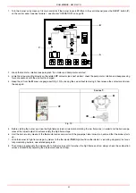
Electrical connections
To connect the burner, please refer to the wiring diagram.
To execute the electrical connections, proceed as follows:
1
remove the cover from the electrical board, unscrewing the fixing screws;
2
execute the electrical connections to the supply terminal board as shown in the attached wiring diagrams,
3
check the direction of the fan motor and pump motor (see next pargraph)
4
refit the panel cover
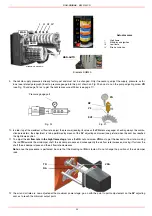
Rotation of fan motor and pump motor
Once the burner’s electrical connection is accomplished, remember to check the rotation of the fan and pump motors. The motor
should rotate in counterclockwise direction looking at motor’s cooling fan. In case of incorrect rotation, reverse the three-phase supply
and check again the rotation of the motor.
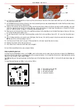
Installation diagram of light oil pipes
PLEASE READ CAREFULLY THE “WARNINGS” CHAPTER AT THE BEGINNING OF THIS MANUAL.
Respect the basic safety rules. make sure of the connection to the earthing system. do not reverse the phase and
neutral connections. fit a differential thermal magnet switch adequate for connection to the mains.
ATTENTION: before executing the electrical connections, pay attention to turn the plant’s switch to OFF and be
sure that the burner’s main switch is in 0 position (OFF) too. Read carefully the chapter “WARNINGS”, and the
“Electrical connections” section.
WARNING: The burner is provided with an electrical bridge between terminals 6 and 7; when connecting the high/
low flame thermostat, remove this bridge before connecting the thermostat.
IMPORTANT: Connecting electrical supply wires to the burner teminal block MA, be sure that the ground wire is
longer than phase and neutral ones.
CAUTION: adjust the thermal cut-out according to the motor rated current value.
Fig. 5 - Double-pipe system
The burner is supplied with filter and flexible hoses, all the parts upstream the filter and downstream the return flexible hose, must be
installed by the customer. As far as the hoses connection, see the related paragraph.
Key
1
Burner
2
Flexible hoses (fitted)
3
Light oil filter (fitted)
4
Automatic interceptor (*)
5
One-way valve (*)
6
Gate valve
7
Quick-closing gate-valve (outside the tank or boiler rooms)
(*) Only for installations with gravity, siphon or forced
circulation feed systems. If the device installed is a
solenoid valve, a timer must be installed to delay the
valve closing.
The direct connection of the device without a timer
may cause pump breaks.
From tank
To tank
Содержание RG1025
Страница 2: ......
Страница 18: ...C I B UNIGAS M039144CD 18 BERGONZO NOZZLES Fig 15 ...
Страница 19: ...C I B UNIGAS M039144CD 19 Fig 16 ...
Страница 20: ...C I B UNIGAS M039144CD 20 Fig 17 ...
Страница 21: ...C I B UNIGAS M039144CD 21 Fig 18 ...
Страница 38: ......
Страница 39: ......


