


C.I.B. UNIGAS
- M039144CD
10
spacer to move the burner backwards or to design a blast tube tha suites the utilisation (please, contact the manifacturer).
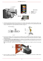
Fitting the burner to the boiler
To perform the installation, proceed as follows:
1
drill the furnace plateas decribed in paragraph (“Overall dimensions”);
2
place the burner towards the furnace plate: lift and move the burner by means of its eyebolts placed on the top side (see”Lifting and
moving the burner”);
3
screw the stud bolts (5) in the plate holes, according to the burner’s drilling plate described on paragraph “Overall dimensions”;
4
place the ceramic fibre plait on the burner flange;
5
install the burner into the boiler;
6
fix the burner to the stud bolts, by means of the fixing nuts, according to the picture below.
7
After fitting the burner to the boiler, ensure that the gap between the blast tube and the refractory lining is sealed with appropriate
insulating material (ceramic fibre cord or refractory cement).
;
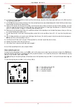
Pilot gas train
Fig. 4
Key
1
Burner
2
Gas valves
3
Minimum gas pressure switch
4
Gas pressure governor with filter
5
Bellow joint
6
Manual cutoff valve
Fig. 3
Key
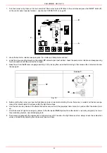
a) Heat output in kW
b) Length of the flame tube in meters
c) Flame tube firing intensity in MW/m
3
d) Combustion chamber diameter (m)
Fig. 4 - Firing intensity, diameter and lenght of the test flame tube as a function of the heat
input in kW.
Keys
1
Burner
2
Fixing nut
3
Washer
4
Ceramic fibre plait
5
Stud bolt
7
Blast tube
4
1
2
2
3
4
5
6
MANUFACTURER
INSTALLER
Содержание RG1025
Страница 2: ......
Страница 18: ...C I B UNIGAS M039144CD 18 BERGONZO NOZZLES Fig 15 ...
Страница 19: ...C I B UNIGAS M039144CD 19 Fig 16 ...
Страница 20: ...C I B UNIGAS M039144CD 20 Fig 17 ...
Страница 21: ...C I B UNIGAS M039144CD 21 Fig 18 ...
Страница 38: ......
Страница 39: ......