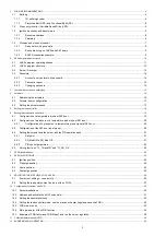
Unigas K990A Скачать руководство пользователя страница 56

12 

2.2 

LMV5x program structure 


Содержание K990A

Страница 1: ...M039611CA 0 1 11 2021 BURNERS BRUCIATORI BRULERS BRENNER QUEMADORES MANUAL OF INSTALLATION USE MAINTENANCE Microprocessor controlled LMV5x Gas burners K750A K890A K990A...

Страница 2: ...non original components whether spare parts kits accessories and optionals Force majeure Furthermore the manufacturer declines all responsibility for non compliance with this manual Personnel training...

Страница 3: ...rner shut down reser the control box by means of the RESET pushbutton If a second shut down takes place call the Tech nical Service without trying to RESET further The unit shall be operated and servi...

Страница 4: ...UNI EN ISO 12100 2010 Safety of machinery General principles for design Risk assessment and risk reduction For the following information please refer to the data plate Burner type and burner model mu...

Страница 5: ...ve the burner performance by controlling the flame geometry and combustion efficiency Fuel and air are routed through separated channels inside the combustion head then mixed to ignite the flame insid...

Страница 6: ...cial 7 EQUIPMENT 1 2 gas valves gas proving system 8 2 gas valves gas proving system maximum gas pressure switch 8 GAS CONNECTION 65 DN65 80 DN80 100 DN100 125 DN125 9 MICRO PROCESSOR CONTROL ES with...

Страница 7: ...Protection IP40 Operation PR ProgressiveMD Fully modulating Gas train 65 Valves size Gas connection 65 DN65 65 DN65 Gas train 80 Valves size Gas connection 80 DN80 Gas train 100Valves size Gas connect...

Страница 8: ...125 738 175 2073 1347 562 904 754 1192 479 K890A 50 595 101 1672 946 400 440 494 763 614 845 190 65 611 117 1695 969 636 487 292 80 626 132 1728 1002 687 538 875 313 100 639 145 1808 1082 791 642 942...

Страница 9: ...538 875 313 100 639 145 1539 1082 791 642 942 353 125 738 175 1804 1347 562 904 754 1192 479 K890A 50 595 101 1403 946 400 440 494 763 614 845 190 65 611 117 1426 969 636 487 292 80 626 132 1459 1002...

Страница 10: ...mbar ambient temperature at 15 C NOTE The performance curve is a diagram that represents the burner performance in the type approval phase or in the laboratory tests but does not represent the regulat...

Страница 11: ...lues in the diagrams refer to GPL with a calorific value of 22300 kcal Stm3 15 C 1013 mbar and a density of 2 14 kg Stm3 When the calorific value and the density change the pressure values should be a...

Страница 12: ...utlet to get the pressure in the combustion chamber and the other one into the butterfly valve s pressure outlet of the burner On the basis of the measured differential pressure it is possible to get...

Страница 13: ...andling operations must be carried out with appropriate resources and qualified personnel ATTENTION Use intact and correctly dimensioned hoisting equipment conforms to the local regulations and health...

Страница 14: ...the supplier to verify that a correct matching is possible with respect of the application involved To correctly match the burner to the boiler verify the type of the blast tube Verify the necessary i...

Страница 15: ...nt the gas train proceed as follows NOTE the bellows unit the manual cutoff valve and the gaskets are not part of the standard supply WARNING before executing the connections to the gas pipe network b...

Страница 16: ...or VGD and MB DLE 10 Manual valve optional ATTENTION once the gas train is mounted according the gas proving test mus be performed according to the procedure set by the laws in force ATTENTION it is r...

Страница 17: ...es specified by DUNGS are authorised to be used to connect the PS to the VD R Max cable length 3 m A A C B B C 1 Mount flange into pipe systems Use appropriate sealing agent 2 Insert VB together with...

Страница 18: ...ilizer Caution the SKP2 diaphragm D must be vertical WARNING removing the four screws BS causes the device to be unserviceable SA SA TP D BS SKP1 SKP2 SIEMENS VGD Mounting positions TP Siemens VGD con...

Страница 19: ...ect the gas valves group and pressure switches plugs Overall dimensions mm BURNERS WITH INVERTER VARIANT if provided ATTENTION it is reccomended to install the filter with gas flow parallel to the flo...

Страница 20: ...s and with a signal in 0 10V controls it through the inverter Generally the curve of the inverter goes from 50 to 100 of the engine revolutions This in addition to improving the setting of the burner...

Страница 21: ...controls it through the inverter Generally the curve of the inverter goes from 50 to 100 of the engine revolutions This in addition to improving the setting of the burner also allows a saving on the c...

Страница 22: ...e td1 The pressure switch PGCP has not to detect a rise of pressure Test space filling EV1 opens and keep this position for a preset time td3 in order to fill the test space Test gas pressure EV1 clos...

Страница 23: ...e RC circuit Siemens between the terminal 2 terminal X3 04 4 in case of LMV2x LMV3x LMV5x LME7x of the base and the earth terminal RC466890660 For LMV5 control box please refer to the clabeling recomm...

Страница 24: ...E MACHINE EXCEPT FOR ITS MAINTENANCE TO SECURE THE MACHINE ACT ON THE ISOLATOR SWITCH IN CASE OF ANOMALIES THAT REQUIRED A SHUT DOWN OF THE BURNER IT S POSSIBLE TO ACT ON THE AUXILIARY LINE SWITCH LOC...

Страница 25: ...the test is performed the proving system LED turns on At the end of the test the burner staring cycle begins in case of leakage in a valve the gas proving system stops the bur ner and the lamp B1 turn...

Страница 26: ...ety chain is open waiting for the startup enabling signal standby Program phase no 12 Main page 3 check the fan motor rotation see related paragraph 4 make the safety chain enabling the system to star...

Страница 27: ...tems Normal operation by selecting this item and pressing the ENTER key the main page is showed press ESC to go back to the main menu Status Reset it shows system errors or faults occuring it represen...

Страница 28: ...age enter the main menu by pressing the ESC key twice by means of the arrow keys select Params Display press ENTER the system will ask you to enter the proper password by means of the arrow keys selec...

Страница 29: ...the 2 position controller To set these values select the item SD_ModOn SDOn by scrolling down the Load controller menu with the arrow keys and press ENTER the display will show The deafult value for...

Страница 30: ...ime Winter WIN Time operation and the continent EU Europe US United States choose the Summertime Wintertime mode desired and cofirm by pressing ENTER press ESC to exit Set the time zone Time EU US in...

Страница 31: ...This function is already set by the Technical service access by reserved password if this function is enabled when the burner starts upthe Thermal shock protection activated message will be showed If...

Страница 32: ...s ratio curvepoints setting procedure on the LMV manual Check con tinuosly the flue gas analisys to avoid combustion with air excess Once the butterfly valve is completely opened acting on the pressur...

Страница 33: ...nts do not exceed a value that creates a hazardous condition to the burner Adjusting output pressure for positive pressure systems requires PS 10 40 or PS 50 200 Outlet pressure MIN 10 25 50 75 MAX PS...

Страница 34: ...ed To calibrate the maximum pressure switch proceed as follows according to its mounting position remove the pressure switch plastic cover if the maximum pressure switch is mounted upstreaam the gas v...

Страница 35: ...he plant during the commissioning The factory setting depends on the type of fuel for which the burner is designed For natural gas burners plate holes are fully opened Center head holes gas flow regul...

Страница 36: ...HE FUEL MANAUL CUTOFF VALVES CLOSED ATTENTION READ CAREFULLY THE WARNINGS CHAPTER AT THE BEGINNIG OF THIS MANUAL DANGER Incorrect motor rotation can seriously damage property and injure people ATTENTI...

Страница 37: ...as shown in figure Note for the subsequent assembly carry out the above described operations in the reverse order checking the correct position of the OR ring Fig 6 position to push 1 2 3 4 5 6 7 1 P...

Страница 38: ...em place the new electrodes being careful to observe the measures showed on pag reassemlbe following the reversed procedure Caution adjust the nozzle position according to the air pipe by means of the...

Страница 39: ...owner makes the decision whether to finish using the burner or replacing and disposing of it based on the actual state of the appliance and any repair costs The use of the burner for other purposes af...

Страница 40: ...burner control BURNER LOCKS OUT WITHOUT ANY GAS FLOW Gas valves don t open Check voltage on valves if necessary replace valve or the burner control Check if the gas pressure is so high that the valve...

Страница 41: ...PART IV MAINTENANCE 41...

Страница 42: ......

Страница 43: ......

Страница 44: ...a L Galvani 9 35011 Campodarsego PD ITALY Tel 39 049 9200944 Fax 39 049 9200945 9201269 web site www cibunigas it e mail cibunigas cibunigas it Note specifications and data subject to change Errors an...

Страница 45: ...Siemens LMV5x Service Manual M12920CC rev 2 1 08 2017...

Страница 46: ...harmful Before any cleaning or servicing operation disconnect the unit from the mains by turning the master switch OFF and or through the cut out devices that are provided Make sure that inlet or exh...

Страница 47: ...2 Configuration of a pressure or a temperature probe type at X61 door 20 6 2 1 Configuration of a pressure or a temperature probe signal at X61 door 20 6 3 Configuration of the X62 door input signal...

Страница 48: ...must be connected to earth PE Volt must be 0 V between N PE NOTE PE protection earth it is not FE FE functional earth 1 1 2 Protective Earth PE and Functional Earth FE Protective Earth PE Known as an...

Страница 49: ...les and to the burner housing e g use a electrical insulating conduit or distance parts e g plastic material see also Appendix Example for wiring earthing and shielding the LMV5 System Prefer a double...

Страница 50: ...lso Appendix Example for wiring earthing and shielding the LMV5 System 1 3 2 Shielding The LMV5 FE terminals for the shields are LMV5 internally connected with X52 4 this terminal must be connect exte...

Страница 51: ...ables for the Load controller Temperature or Pressure sensor set point load output at the LMV5 X60 X61 X62 X63 Together in cable duct 2 for Line voltage e g Cable for Ignition transformer Cables for o...

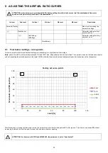
Страница 52: ...8...

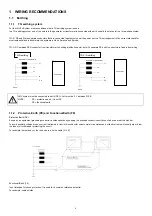
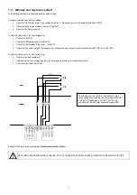
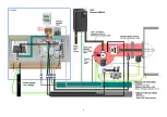
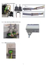
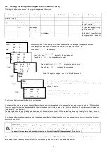
Страница 53: ...9 1 4 1 Servomotor wiring example 1 4 2 Bus cable wiring on LMV5x and AZL doors 1 4 3 EARTH connection example...

Страница 54: ...urner will immediately turns off keys socket The user interface is made of display it shows menus and parameters ESC key previous level it goes back to the previous level menu or exits the programming...

Страница 55: ...ition position phase 38 The burner remains in that position because this is the only one work point in memory The fuel air ratio curve must be set until the maximum load limit 100 output During the se...

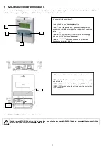
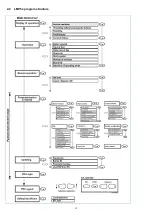
Страница 56: ...12 2 2 LMV5x program structure...

Страница 57: ...ED TO NOT USE O2 MONITORING IF FGR IS INSTALLED AND ACTIVE 2 3 Burner ID number The burner ID number corresponds to the burner serial number NOTE in case of call to the Service Center always tell the...

Страница 58: ...rmed by pressing Enter Display before the first password character is entered Enter Password The example displays when entering the third password character Enter Password S If the check of the passwo...

Страница 59: ...nals 318 and 319 of the burner supply terminal block see below the system will lead to an immediate burner lockout In case of burner designed with automatic pull out system from the generator the burn...

Страница 60: ...address an actuator choose the corresponding actuator and follow the instructions on display When the actuator green LED flashes it means that one of the following function is set according to the nu...

Страница 61: ...o according to the next procedure By following the next table set both parameter OperatRampMod and TimeNoFlame to set the ramp up stop times for the VSD and the actuator opening speed from 0 to 90 Fol...

Страница 62: ...al output from the LMV to the client DCS or PLC Output Value Selection are Load Load 0 O2 Pos Air Pos Fuel Pos Aux1 Pos Aux2 Pos Aux3 Speed VSD Flame Temp Pt1000 TempNi1000 Temp Pt100 Temp X61 Press X...

Страница 63: ...level 5th level 6th level Description Params Display Menu level for making the parameter set tings LoadController Settings for the internal load controller Configuration General configuration of the l...

Страница 64: ...ens End of pressure measuring range for input X61 0 99 9 bar 0 2000 C 0 99 9 bar 0 2000 C Set the probe value Example if a max 10bar Siemens sensor is used the voltage output signal will be 0 V at 0 b...

Страница 65: ...6th level Description Params Display Menu level for making the t Params Display SD ModOn General configuration of the load SD ModOn SD ModOff General configuration of SD ModOff the display will show T...

Страница 66: ...for internal load controller StandardParam Adaption very fast fast normal slow very slow It is possible to manually set the PID parameters to any value in the setting range shown below to activate a...

Страница 67: ...100 Ni1000 or Pt 1000 temperature sensor is connected to X60 3 and X60 4 terminals ATTENTION basically these parameters provide a function similar to the safety thermostat one but can not replace it T...

Страница 68: ...of the menu by means the Esc 1st level 2nd level 3rd level 4th level 5th level Range Description Params Display Menu level for making the parameter settings VSD Module Settings for the VSD module Conf...

Страница 69: ...ogramming levels of the menu by means the Esc 1st level 2nd level 3rd level 4th level 5th level 6th level Description Params Display Menu level for making the para meter set tings RatioControl GasSett...

Страница 70: ...corresponding to a hypothetic low flame stage Note points P1 and P2 are temporally mentioned 10 and 100 load independently from the actual load The operator can name the load on each point without re...

Страница 71: ...of oil ATTENTION as for increasing by few degrees it means that the increasing must be performed in order to avoid great excess of air or defect of air Therefore the increasing operation must be perfo...

Страница 72: ...ir actuator Do not exit by pressing Esc from the values column because data will not be stored Press arrows to select another actuator to be set for example press to choose Fuel Press keys to change t...

Страница 73: ...the other points So it is necessary to check the adjustment of the points already set ATTENTION for proper operation it is necessary that the curve of each actuator does not reverse its slope ATTENTI...

Страница 74: ...cts are the following 1 Pressures have reciprocal effects 2 The reduction of O2 can lead to a significant increase of NOx levels As a result of these reciprocal effects it is difficult if not impossib...

Страница 75: ...ngs for firing on Gas or on Oil AirActuator GasActuat OilActuat AuxActuator AuxActuator 2 AuxActuator 3 AuxActuator 3 AuxActuator 3 MUST be chosen After the addressing activate the FGR servomotor 1st...

Страница 76: ...Open 10 4 Setting the load controller mode see the previous chapter regolazione senza FGR WARNING If one of the intLC internal Load Controller option must be choice a temperature sensor cannot be con...

Страница 77: ...ulation temperature Auxiliary actuator 3 maintains the ignition position until an adjustable temperature is reached parameter FRG On Temp During the operation the burner regulate its load as per the s...

Страница 78: ...inimum amount of flue gas The position is also used to ensure a defined damper position for emergency operation or automatically deactivated flue gas recirculation FGR FGR MaxPos Fact Maximum limitati...

Страница 79: ...on FGR factor of 50 leads to a 50 reduction of the damper positions If the temperature value of the smoke during the operation of the burner is higher than the temperature value during the commissioni...

Страница 80: ...StageLoad 0 100 15 StageSetp_M od 1 100 Wcurrent 5 Stage Setp_Stage 1 100 Wcurrent 5 MaxTme Mod 1 63 min 3 min MaxTmeStage 1 63 min 3 min Cold start thermal shock protection maximum time per step mult...

Страница 81: ...tion this function can be set at user level also see chapter manual operation the CSTP function is momentary excluded when enabling the automatic operation again the CSTP function previously set at Se...

Страница 82: ...assword Description ManualOpe ration Menu level for activating manual operation with the preselected load Au tom Manual Off Selection of manual or automatic operation Automatic Burner on Burner off Us...

Страница 83: ...39...

Страница 84: ...V 10 15 50 60 Hz Imax 5 A PIN3 x Protective earth PE PIN4 x Supply voltage neutral conductor N PIN5 x Supply voltage live conductor L AC 230 V 10 15 50 60 Hz fuse 6 3 AT DIN EN 60 127 2 5 X4 01 Fuel s...

Страница 85: ...5 mA PIN2 x Controller closes stage 3 AC 230 V 10 15 50 60 Hz Imax 1 5 mA PIN3 x Controller opens stage 2 AC 230 V 10 15 50 60 Hz Imax 1 5 mA PIN4 x Power signal for control of con troller AC 230 V 10...

Страница 86: ...ductor N PIN3 Fuel valve 2 oil AC 230 V 10 15 50 60 Hz 1 A cos 0 4 X7 02 PIN1 x Protective earth PE PIN2 x Neutral conductor N PIN3 Fuel valve 3 oil AC 230 V 10 15 50 60 Hz 1 A cos 0 4 X7 03 PIN1 x Pr...

Страница 87: ...oil AC 230 V 10 15 50 60 Hz 1 A cos 0 4 X9 01 PIN4 x Fuel valve 1 gas AC 230 V 10 15 50 60 Hz 2 A cos 0 4 PIN3 x Fuel valve 2 gas AC 230 V 10 15 50 60 Hz 2 A cos 0 4 PIN2 x Fuel valve gas AC 230 V 10...

Страница 88: ...vely QRA2 QRA4 U QRA10 refer to section Description of inputs and out puts Umax X3 04 PINS Imax 0 5 mA X50 PIN6 x Reference ground PELV PIN5 x Communication signal CANL DC U 5 V Rw 120 level to ISO D...

Страница 89: ...mperature sensor input PT100 X61 PIN5 x Functional earth for shield connec tion PIN4 x Reference ground PIN3 x Current input for temperature pressure signal 0 4 20 mA DC 0 4 20 mA PIN2 x Voltage input...

Страница 90: ......

Страница 91: ......

Страница 92: ...Note Specifications and data subject to change Errors and omissions excepted...

Страница 93: ...d an earth external wire for the motor ground The cable for the 4 20mA signal that controls the VSD must be shielded only LMV5x side ends connected to the equipotential terminal If the VSD is not insi...

Страница 94: ...Annex1 Example for motor cable...

Страница 95: ......

Страница 96: ...Annex 2 Example for sensor cable...

Страница 97: ......

Страница 98: ......

Страница 99: ...E Power supply Line voltage Gas L1 High Voltage Transformer N M Power supply Line voltage FE X73 Speed sensor VSD Fan Motor Separate conduit shielded line voltage cable X70 X10 02 X9 01 X4 02 Separate...

Страница 100: ...ion and current fuel throughput The LMV52 system uses an O2 sensor QGO20 an external O2 module and the standard components of the LMV51 sys tem The PLL O2 module is a detached measuring module for the...

Страница 101: ...defined system cables AGG5 641 and AGG5 631 result from the points of intersection in the graph 50 48 46 44 42 40 38 36 34 32 30 28 26 24 22 20 18 16 14 12 10 8 6 4 2 0 0 5 1 25 2 3 5 7 8 AGG5 631 AG...

Страница 102: ......

Страница 103: ...CAN bus cable 100 m Whenever the distance between the LMV5 and the last actuator exceeds 20 m or if more than one SQM48 is used on the burner refer to sizing chart Determination of maximum cable leng...

Страница 104: ...N F T4 AC2 12 V 5 5 3 Not used M L Power trafo 2 AGG5 2 No bus termination No bus termination Bus termination 5 5 5 5 No bus termination No bus termination Installation in the control panel actuator...

Страница 105: ...owered by a sec ond transformer to be located near the actuators and the O2 module Connect the power supply line from that transformer to the O2 module PLL52 in ex ample 3a SA6 in example 3b Auxiliary...

Страница 106: ...n facility 18 8 1 Inputs and outputs Mounting panel shielding connection Communication and power supply for LMV52 Mounting panel shielding connection Communication and power supply Temperature sensor...

Страница 107: ...l o w e d t o j o i n t h e f l u e g a s e s o n t h e i r w a y f r o m t h e b u r n e r t o t h e d e t e c t o r D F l o w v e l o c i t y 1 1 0 m s F l u e g a s t e m p e r a t u r e a t t h e...

Страница 108: ...e p o u r B 1 B 2 B 2 T e n s i o n d e t h e r m o c o u p l e M U 3 S i g n a l d e l l m e n t d e c p m p e n s a t i o n d e t e m p r a t u r e G 2 A l i m e n t a t i o n d e l l m e n t d e c...

Страница 109: ...k s i t i s r e c o m m e n d e d t o l e a v e t h e m e a s u r i n g s y s t e m Q G O a n d R P O s w i t c h e d o n D u r i n g t h e h e a t i n g u p p h a s e t h e d e t e c t o r c o u l d...

Страница 110: ...A G O 2 0 0 0 2 A A R a u c h g a s e i n t r i t t B R a u c h g a s a u s t r i t t C K e r b e D F l a c h d i c h t u n g b e i l i e g e n d L 1 8 0 m m f o r A G O 2 0 0 0 1 A L 2 6 0 m m f o r...

Страница 111: ...r h Transport DIN EN 60 721 3 2 Climatic conditions class 2K2 Mechanical conditions class 2M2 Temperature range 30 70 C Humidity 95 r h Operation DIN EN 60 721 3 3 Climatic conditions class 3K5 Mecha...

Страница 112: ...GND SHIELD 12VAC1 12VAC2 CANH CANL GND SHIELD AZL5 x FE FE SQM4 LMV52 Brown brn White wh Yellow yl Green grn Black blk Brown brn White wh Yellow yl Green grn Black blk Flue gas temperature PLL52 PLL5...

Отзывы: