


PART III: OPERATION
26
AIR FLOW AND FUEL ADJUSTMENT
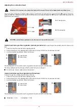
Adjustments - brief description
The air and fuel rates adjustments must be performed at the maximum ouptput first (“high flame”): see the LMV5.. related manual..
Check that the combustion parameters are in the suggested limits.
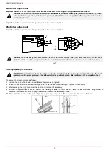
Check the flow rate measuring it on the counter or, if it was not possible, verifying the combustion head pressure by means of a dif-
ferential pressure gauge, as described on par. “Measuring the gas pressure in the combustion head”.
Then, adjust the combustion values by setting the “gas/air” ratio” curvepoints (see the LMV5.. related manual).
Set, now, the low flame output, in order to avoid the low flame output increasing too much or that the flues temperature gets too low
to cause condensation in the chimney.
Start-up procedure
1
Turn the burner on.
2
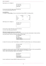
the LMV control box starts the system test cycle: the AZL display shows the
System Test
message; at the end of the test, it shows
the main page and the system stops (the safety chain is open) waiting for the startup enabling signal (standby - Program phase no.
12)
Main page
3
check the fan motor rotation (see related paragraph).
4
make the safety chain enabling the system to start up
5
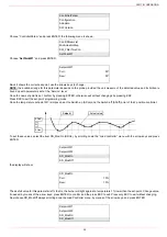
the combustion cycle starts: the system will show the operating stages
- Prepurging
(program phase no.30)
- Driving to ignition position
(program phase no.36)
- Ignition position
(program phase no.38)
- Fuel
(the fuel solenoid valves open)
- Flame
(the flame lights up)
- Driving to low flame
(the actuator drives to low flame).
NOTE:
the
C
and
A
, on the .
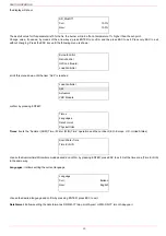
Once the ignition cycle ends, the main page is shown:
Main page
Set point:
temperature set-point
WARNING! During commissioning operations, do not let the burner operate with insufficient air flow (danger of
formation of carbon monoxide); if this should happen, make the fuel decrease slowly until the normal combustion
values are achieved.
WARNING! the combustion air excess must be adjusted according to the values in the following chart.
Recommended combustion parameters
CO
2
(%)
O
2
(%)
Fuel
Recommended (%) CO
2
Recommended (%) O
2
Natural gas
9 ÷ 10
4,8 ÷ 3
LPG
11 ÷ 12
4,3 ÷ 2,8
Setpoint
80°C
Act.value
78°C
Fuel
GAS
Standby
12
Setpoint
80°C
Act.value
78°C
Load
24%
Flame
60%
Содержание K990A
Страница 41: ...PART IV MAINTENANCE 41...
Страница 42: ......
Страница 43: ......
Страница 45: ...Siemens LMV5x Service Manual M12920CC rev 2 1 08 2017...
Страница 52: ...8...
Страница 53: ...9 1 4 1 Servomotor wiring example 1 4 2 Bus cable wiring on LMV5x and AZL doors 1 4 3 EARTH connection example...
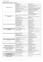
Страница 56: ...12 2 2 LMV5x program structure...
Страница 83: ...39...
Страница 90: ......
Страница 91: ......
Страница 92: ...Note Specifications and data subject to change Errors and omissions excepted...
Страница 94: ...Annex1 Example for motor cable...
Страница 95: ......
Страница 96: ...Annex 2 Example for sensor cable...
Страница 97: ......
Страница 98: ......
Страница 102: ......


