


28
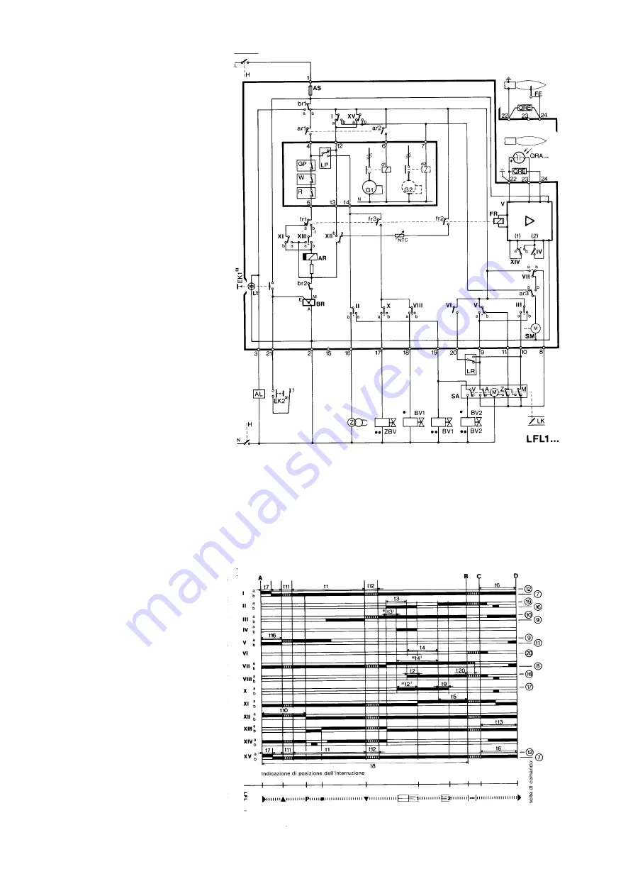
Key:
A
limit contact switch for damper OPEN
position
AI
advance signal of a block
AR
main relay (working network) with
contacts “ar”
AS
Monitor fuse
BR
block relay with “br” contacts
BV
fuel valve
EK
reset button
FE
detector electrode of ionisation circuit
FR
flame relay with “fr” contacts
G
ventilator motor or burner motor
GP
gas pressostat
H
main interruptor switch
L
block stoppage LED
LK
damper
LP
air pressostat
LR
safety regulator
M
auxiliary contact switch for damper
“MIN” position
QRA
UV detector
QRE
ignition spark detector
R
thermostat or pressostat
S
fuse
SA
damper servo-motor
SM
synchronous programmer motor
V
flame signal amplifier
V
in case of servo-motor: auxiliary contact
for response to fuel valve re damper
position
W
safety pressostat or thermostat
Z
ignition transformer
Z
in case of servomotor: end of limit
contact switch for damper CLOSED
position
ZBV
pilot burner fuel valve
°
for mono-tube burners
°°
for twin-tube burners
(1
)input for raising QRA detector voltage
to test level
(2)
input for excitation of flame relay during
flame detector
t e s t
circuit (contact XIV) and during safety
time (contact I
V)
(3)
Do not press EK for more than 10
seconds
Programmer diagram
t1
pre-ventilation time
t2
safety time
*t2'
1st safety time
t3
pre-ignition time
*t3'
pre-ignition time
t4
interval for creating current between
terminals 18 and 19
*t4'
interval for creating current between
terminals 17 and 19
t5
interval for creating current between
terminals 19 and 20
t6
post-ventilation time
t7
interval between response and current
created at terminal 7
t8
duration of start-up
*t9
2nd safety time
t10
interval before air pressure monitoring
begins
t11
damper opening travel time
t12
damper closure travel time
t13
permissible post-combustion time
t16
initial delay of damper OPEN response
t20
interval before programmer
automatically stops
* These times are valid with the use of a series
01 safety device for monitoring burners with
intermittent pilot lighter.
APPENDIX
Содержание HP60
Страница 4: ......
Страница 5: ......
Страница 24: ...24 MAINTENANCEMANUAL ELECTRICAL DIAGRAM code 05 483 Rev 03...
Страница 25: ...25 MAINTENANCEMANUAL...
Страница 32: ...32 MONARCH OIL NOZZLE Mod F80 BPS APPENDIX...
Страница 33: ...33 BERGNZO OIL ZOZZLE Mod A3 APPENDIX...
Страница 34: ...34 FLUIDICS OIL NOZZLE Mod K3 APPENDIX...
Страница 35: ...35 FLUIDICS OIL NOZZLE Mod KC2 APPENDIX...