background image


64 Bays SAS to SAS/SATA JBOD Subsystem


18 

User Manual 


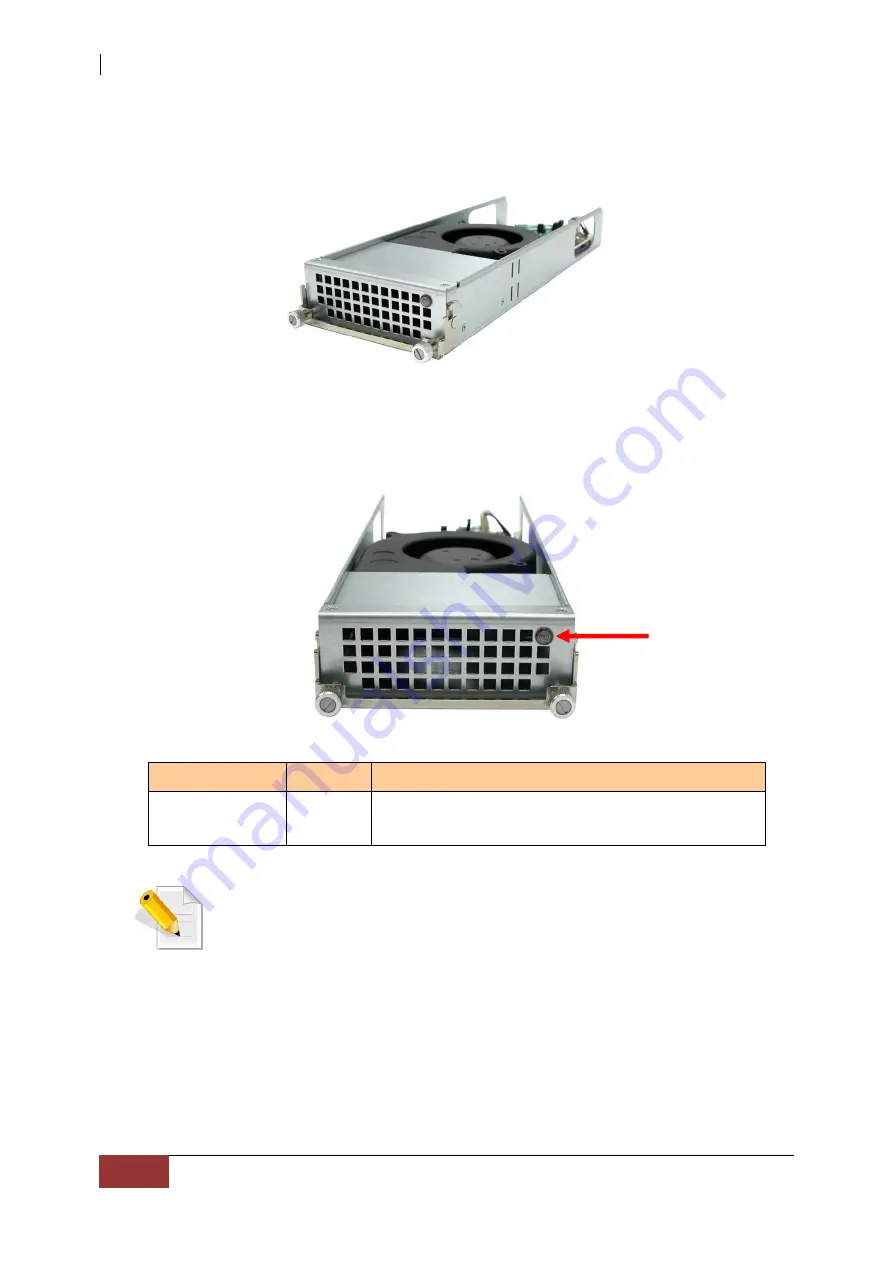
2.4.1   Turbo Fan 

The turbo fan (Fan 6) provides additional airflow inside the enclosure. 


Turbo Fan LED 


Indicator 

Color 

Description 

Status LED 

Red 

Indicates the turbo fail is faulty.  


NOTE: The status of Turbo Fan (Fan 6) is monitored by Expander 
Module 1.


Status LED 

Содержание Proware EP-4646JD-SCSC

Страница 1: ...64 Bays SAS to SAS SATA JBOD Subsystem User Manual Revision 1 0...

Страница 2: ...LEDs 10 2 1 1 3 Menu Diagram 11 2 1 2 Rear View 12 2 3 Power Supply Fan Module PSFM 13 2 3 1 PSFM Panel 15 2 4 Fan Module 16 2 4 1 Turbo Fan 18 2 5 Disk Drive Installation into the Disk Slot 19 2 5 1...

Страница 3: ...on may be reproduced stored in a retrieval system or transmitted in any form or by any means electronic mechanical photocopying recording or otherwise without the prior written consent Trademarks All...

Страница 4: ...te the installation site temperature making it not to exceed the allowed ambient temperature Before plugging in any power cords cables and connectors make sure that the power switches are turned off D...

Страница 5: ...he shipping carton contains the following NOTE If any damage is found contact the dealer or vendor for assistance JBOD Subsystem Unit 64 pairs of HDD side brackets Two 2 Power cords Two 2 mini SAS HD...

Страница 6: ...system maintenance and management Highest Density Available 4U chassis with 64 bays carriers Support the 3 5 enterprise class SAS3 SATA3 HDD drives High Availability Dual SAS Expander JBOD consist of...

Страница 7: ...ctor 4U of Hot Swap Trays 64 Tray Lock Yes Disk Status Indicator Access Fail LED Disk Backplane SAS3 SATA3 of PS Fan Modules 1100W x 2 w PFC of Fans 15 Monitor port support Yes Power requirements AC 9...

Страница 8: ...g Parts of the JBOD Subsystem 2 1 Main Components 2 1 1 Front View IMPORTANT When powering off the JBOD subsystem turn off first the Main Switch and allow at least 4 minutes for the subsystem to shutd...

Страница 9: ...Main Switch Button Flashing Blue Indicates that the power cords are inserted and or indicates the 2 power supply switches are turn on Light Blue Indicates that the sytem is on No Light Indicates that...

Страница 10: ...icator Color Description Activity LED Blue Blinking Indicates the disk drive is busy or being accessed Power On Fail LED Green Indicates the disk drive in this slot is good RED Indicates the disk driv...

Страница 11: ...p2 35 C Chip3 31 C Chip4 30 C HDD01 33 C HDD64 30 C Power Status Power01 Good Good Power02 Good FAN Status Fan 1 3970 rpm Good Fan 2 3970 rpm Fan15 3970 rpm Voltage Status 1 5V_ 4 94V Good 1 12V_ 12 1...

Страница 12: ...nder module Connect the serial cable RJ11 to DB9 to your system s serial port for Expander 1 Expander CLI B1 B2 RS 232 Port Use to upgrade the firmware of the expander module Connect the serial cable...

Страница 13: ...ns two 1100W Power Supply Fan Modules All PSFM are inserted at the rear of the chassis Front Panel Rear Side NOTE Each PSFM delivers Full Range 100V 240V 10 voltage AC electricity Each PSFM consists o...

Страница 14: ...fans Fan 1 and Fan 2 on the front panel and Fan 3 Fan 4 and Fan 5 on the rear side The second PSFM Power Supply 2 on the right side has five fans also Fan 7 and Fan 8 on the front panel and Fan 9 Fan...

Страница 15: ...s in the PSFM has failed When the power cord connected from main power source is inserted to the AC Power Input Socket the Power Status LED becomes RED When the switch of the PSFM is turned on the LED...

Страница 16: ...ays SAS to SAS SATA JBOD Subsystem 16 User Manual 2 4 Fan Module The 64bay JBOD subsystem contains 15 fans Front Panel Rear Side Fan 1 Fan 2 Fan 7 Fan 8 Power Supply 1 Power Supply 2 Front Panel Rear...

Страница 17: ...64 Bays SAS to SAS SATA JBOD Subsystem User Manual 17 Indicator Color Description Fan Fault LED No light Indicates the fan is normal Red Indicates the turbo fail is faulty...

Страница 18: ...4 1 Turbo Fan The turbo fan Fan 6 provides additional airflow inside the enclosure Turbo Fan LED Indicator Color Description Status LED Red Indicates the turbo fail is faulty NOTE The status of Turbo...

Страница 19: ...are not placed in the disk slots If all disk trays will be used to install all 64 disk drives for quicker and easier installation of disk drives in the Disk Array it is recommended to attach first eac...

Страница 20: ...NOTE In dual SAS Expander mode it is strongly recommended to use SAS hard drive disks 2 5 1 To install a disk drive in a disk tray 1 Prepare the HDD side brackets Remove them from the dummy disk by pu...

Страница 21: ...AS SATA JBOD Subsystem User Manual 21 2 Place the brackets on both sides of the disk drive and secure them with screws 2 screws 6 32 UNC L 5 0mm 3 Place the drive carefully in the disk slot 2 screws 6...

Страница 22: ...64 Bays SAS to SAS SATA JBOD Subsystem 22 User Manual 4 Tighten the thumbscrews on the sides of the disk drive...

Страница 23: ...e sections on how to remove the power supply modules and how to remove the disk trays disk drives NOTE The sample model used in the following installation might not be the actual model for this manual...

Страница 24: ...les of the front left side of the rack post Rack Post Front Left Side 4 Insert three 3 M5 nuts on the 2 holes of the front right side of the rack post Rack Post Front Right Side Position of M5 nuts on...

Страница 25: ...il Assembly 6 Hold one rail assembly and install in the front left side of rack To install align and insert the 2 latches of the rail into the 2 holes on the rack post Use the Lock Lever to lock the r...

Страница 26: ...Manual View from Front Side of Front Left Rack Post Lock Lever is Locked View from Rear Side of Front Left Rack Post 2 Latches are inserted in the 4th and 6th holes from bottom M5 nut Lower M5 Nut Loc...

Страница 27: ...sert the 2 latches on the 2 holes on the rear rack post and then push the rail a little towards the rear side and lock the lock lever on the rack post View from Rear Side of Rear Left Rack Post View f...

Страница 28: ...peat step 6 to install the other rail assembly into the right front side View from Front Side of Front Right Rack Post Lock Lever is Not Locked View from Front Side of Front Right Rack Post Lock Lever...

Страница 29: ...t Rack Post 2 Latches are inserted in the 4th and 6th holes from bottom M5 nut 9 Repeat step 7 to install the other end of rail assembly to the rack post of rear right side View from Rear Side of Rear...

Страница 30: ...64 Bays SAS to SAS SATA JBOD Subsystem 30 User Manual View from Rear Side of Rear Right Rack Post View from Rear Side of Rear Right Rack Post Lock Latches Lock Lever Latches...

Страница 31: ...ystem User Manual 31 10 Pull the 2 middle rail members out from the rail assembly Middle Rail Member of Rail Assembly on Left Side of Rack View from Rear Side Rear Left Side Front Left Side Front Side...

Страница 32: ...e 2 middle rails so that 2 inner rails will insert and slide easily Use hands to guide the inner rails when inserted into the middle rails Inner Rail Aligned with and Inserted into the Middle Rail Imp...

Страница 33: ...s the blue locks on both sides of the inner rail members at the same time Then push the enclosure inwards or backwards until it goes inside the rack View from Right Side of Enclosure Blue Lock of Inne...

Страница 34: ...64 Bays SAS to SAS SATA JBOD Subsystem 34 User Manual View from Rear Side of Rack Cabinet Enclosure is Pushed Inwards 13 Insert the power supply modules...

Страница 35: ...each corner Note that the screw driver will need to pass through the corner hole of front panel for the two upper corner holes on both sides Front Left Side Front Right Side 15 Open the top cover and...

Страница 36: ...OD Subsystem 36 User Manual 3 2 Removing the Disk Array from the Rack 1 Remove the six screws in the front corner Front Left Side Front Right Side 2 Remove the power supplies in the rear and the disk...

Страница 37: ...64 Bays SAS to SAS SATA JBOD Subsystem User Manual 37 3 Carefully pull the subsystem 4 Push the white lock to release the subsystem from the rail...

Страница 38: ...S cable to the SAS In Port of the JBOD subsystem enclosure and the other end to the SAS Expansion Port of the RAID subsystem enclosure 3 4 Preparing the JBOD and Connecting to SAS HBA in Host System 1...

Страница 39: ...r 1 second all Activity LEDs will flash once When the power cord s is are disconnected from AC Power Input Socket after 3 seconds all Activity LEDs will flash twice 2 Turn on each Power On Off Switch...

Страница 40: ...h Each disk slot will be checked during subsystem initialization 3 6 Powering Off MPORTANT When powering off the JBOD Subsystem turn off first the Main Switch in the front panel and allow at least 4 m...

Страница 41: ...First is the Expander A1 next is the Expander B1 and A2 then last the Expander B2 NOTE There must be no I O in the disk drives in the JBOD subsystem RAID volumes should not be accessed during firmwar...

Страница 42: ...er A1 RS232 Port and PC COM1 Port or change to other COM Port as necessary 2 Open Windows HyperTerminal Program Connect using COM1 COM Port used in Step1 Baud Rate 115200 n 8 1 Flow Control None 3 Ple...

Страница 43: ...Bays SAS to SAS SATA JBOD Subsystem User Manual 43 5 Select your firmware file path and select Xmodem in the communication protocol and click transfer button 6 Wait for the transfer of file to comple...

Страница 44: ...ys SAS to SAS SATA JBOD Subsystem 44 User Manual 7 When the transfer and firmware update is complete please power cycle the JBOD 8 In command line type system info you can see the Expander firmware ve...

Отзывы: