-----------------------------------------------------------------------------------------------------------------------------------------------------------------------------------------------------------------------------------------------------------------------------------------------------------------------------------------------------------------------------------------------
RU 14
UTV 82
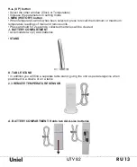
B. WALL-MOUNT RECESSED HOLE: Mount the sensor using the clip on the wall
• PUTTING INTO OPERATION
The communication between the main unit (receiver) and the remote sensor (transmitter)
is wireless, thus simplifying the installation. The remote temperature sensor transmits data
to the main unit, with an operating range of up to 100 feet (30 meters) in opened area.
The remote temperature sensor can be placed indoors or outdoors, depending on the area
where the temperature is intended to be measured. If you intend to measure outdoor
conditions, place the remote sensor outdoors.
Start-up the transmitter-receiver communication:
• It is important to power-up the remote sensor BEFORE powering-up the main unit.
Immediately after batteries are installed, the remote sensor will start transmitting a
temperature data to the main unit.
• It is strongly recommended to power up and test communication between the remote
sensor and the main unit BEFORE permanently mounting the sensor outside.
• During initial set up, place the remote sensor within a range of 1m to the main unit in the
same room, both receiver and transmitter far from any other electric product.
• After reception is established (remote readings will appear on the main unit’s display),
position the remote sensor and the main unit within the maximum transmission range of
up to 30 meters (100 feet).
PLACEMENT OF SENSOR AND MAIN UNIT
• Place the remote sensor so that it faces the main unit (receiver), minimizing obstructions
such as doors, walls and furniture.
• Though the remote sensors are weather-resistant, they should be placed away from direct
sunlight, rain or snow. The optimal location for the outdoor sensor is under the eaves on
the north side of a building with free air circulation.
• The remote sensor can be placed on the flat surface or mounted on the wall in vertical
position by using the included stand. For fixing the stand, use a screw, rather than a nail.
• Ideally, place the remote sensor over soil, rather than asphalt which may affect the
correct measurement.
• Avoid placing the remote sensor near sources of heat, such as chimneys and heating
elements
• Avoid areas that collect heat from the sun and radiate heat, such as metal, brick or
concrete structures, paving, and patios
• The international standard for the valid air temperature measurements is 1.25meters
(4 feet) above the ground
• Make sure that the main unit is locating within the operating range of all remote sensors.
• Ideally the main unit should be placed within line of sight of remote sensors. Avoid
placing the main unit where surfaces emitting and radiating heat (e.g. heating ducts or air
conditioners) and areas with interference from wireless devices (e.g. cordless phones,
radio headsets, baby monitoring devices and other electronics).
• OPERATION
Immediately after batteries are installed, the remote sensor will start transmitting the
temperature data to the main unit in regular intervals.
Once the main unit is powered-up by activating the batteries, the display will show all
available LCD segments for a moment.
Содержание UTV-82
Страница 2: ...RU 2 UTV 82...
Страница 3: ...UTV 82 RU 3 433 0 50 o 0 70 10g C 7 B D...
Страница 4: ...RU 4 UTV 82 1 5 2 A B A B H D G I E F J C K 2 E F 1 2 G H I J K...
Страница 5: ...UTV 82 RU 5 2 6 1 2 Chanel 1 3 2 4 2 20 30 30...
Страница 6: ...RU 6 UTV 82 1 3 12 00 6 8 1 G 3 2 D H 3 3 G 12 24 4 D H 5 G 6 G 2 12 24 1 2 3 4 70 30 5 6...
Страница 7: ...UTV 82 RU 7 H 3 3 D D 0 G 2 3 C F D H Icon Status...
Страница 19: ...161 311110 86 571 86262828...
Страница 20: ......

