background image

Product Specification / User Manual 

Load Amplifier Cassette LVCpro-


© Copyright 2010 TRsystems GmbH , Systembereich Unidor      LVCpro-SV13_E.doc    Version 1.3 /08.11.10    Page 7 of 20 


General Fault Clearance Measures / Shielding 


The  use  of  electronic  sensor  active  systems  in  modern  equipment  requires  a 
consistent  and  correctly  implemented  fault  clearance  and  wiring  concept.  The 
compliance with these requirements is important to ensure the proper function of 
a device with electronic measuring systems. 


Access lines must be laid for remote control and must be separated from supply 
lines stressed with disturbances (shielded). 


Ensure a continuous wiring of the shield as well as an extensive contact between 
the shield and the electric terminals. 


Cable crossings must be avoided.  If inevitable exclusively square crossings shall 
be used. 


In Conclusion 


All information is subject to change. 
The 

TR

systems GmbH / Unidor remains the right of modifications, especially 

regarding the  states  values, dimensions  and  weights  as far  as  they  are  not 
stated elsewhere and lead to product improvements. 
 
All our documentation is protected by copyright. 
The  distribution  to  or  the  use  by  third  parties,  of  parts  or  the  entire 
documentation,  requires  the  written  confirmation  of 

TR

systems  GmbH/ 

Unidor. 


Содержание LVCpro-S

Страница 1: ...H Freiburgerstra e 3 75179 Pforzheim Germany Tel 07231 3152 0 Fax 07231 3152 99 email unidor trsystems de Web http www trsystems de This user manual is kept up to date As the TRsystems GmbH UNIDOR pro...

Страница 2: ...of LVCpro S Advantages Functionality Easy installation and wiring 24VDC supply voltage 2 measuring channels Peak value memory and current value available at the same time Switchable filter for suppre...

Страница 3: ...14 Safety Guidelines and Regulations Technical Specification Block Diagram Terminal Assignment Connector Coding Connection of the Piezo Sensors Setting of the Code Switches Amplification Factors Setti...

Страница 4: ...airs of unqualified workers Disaster situations caused by third parties or force majeure Disclaimer Right of Amendment This user manual is kept up to date As the TRsystems GmbH UNIDOR products are sub...

Страница 5: ...the intended purpose The company TRsystems UNIDOR is not liable for damages caused following other usage Intended use also means only using the device in immaculate condition removing interferences w...

Страница 6: ...responding situations For 24VDC power supplies a safe electric isolation of the low voltage is important Only use power supplies designed acc to IEC 364 4 41 respectively HD 384 04 41 VDE 0100 part 41...

Страница 7: ...trol and must be separated from supply lines stressed with disturbances shielded Ensure a continuous wiring of the shield as well as an extensive contact between the shield and the electric terminals...

Страница 8: ...sistance Output resistance 1015 Ohm 50 Ohm Measuring Window Input Cams Input voltage Input current Function 18 32VDC ca 10mA at 24VDC active high 1 Output low 0 deletes analogous signal Output Data Ou...

Страница 9: ...s 1 Meas Channel 1 Cams 2 Meas Channel 2 0VDC PiezoSensor 2 IN2 GND CASE Input Signal Sensor 2 Analogous Mass Shield PiezoSensor 1 IN1 GND CASE Input Signal Sensor 1 Analogous Mass Shield bottom conne...

Страница 10: ...Load Amplifier Cassette LVCpro S Copyright 2010 TRsystems GmbH Systembereich Unidor LVCpro SV13_E doc Version 1 3 08 11 10 Page 10 of 20 5 Connector Coding 1x 1x 2x 4x Power CAM 1 2 PiezoSensor 1 Piez...

Страница 11: ...nal assignment for tensile load Sensors Connector LVCpro S Core Colour PIN Press Force Sensor 1 Piezosensor 1 red black Shield IN1 GND CASE Press Force Sensor 2 Piezosensor 2 red black Shield IN2 GND...

Страница 12: ...nts will be implemented separately for each channel Channel Sensor Code Switch Function Channel 1 2 SW1 Filter adjustment Channel 1 SW201 Code switch for capacitive rough amplification Piezo Sensor 1...

Страница 13: ...itive amplification Code switch SW201 SW401 Capacity nF Amplification Adjustment Code switch SW202 SW402 Amplification factor times 0 71 8 0 11 12 1 65 0 1 11 08 2 61 8 2 11 03 3 55 0 3 10 96 4 49 8 4...

Страница 14: ...lifier 50 SV3 SV4 P102 P302 8 Settings for DIP Switches or Filters SW1 Channel 1 Piezo Sensor 1 DIP Switch Function ON OFF Default Factory setting with filter F limit 1KHz 1 2 Turn on either only swit...

Страница 15: ...ither of them F limit 1KHz 33nF Default 7 8 OFF 7 F limit 100Hz 220nF II 33nF 7 ON 8 OFF 8 F limit 355Hz 47nF II 33nF 8 ON 7 OFF 9 Commissioning of the LVCpro S Wiring of the piezo sensors Wire the me...

Страница 16: ...ill enable an assessment in case of an overload If replacing the load amplifier cassette LVCpro S it is important to maintain the same adjustment of the code switches otherwise there is the risk of ov...

Страница 17: ...anual Load Amplifier Cassette LVCpro S Copyright 2010 TRsystems GmbH Systembereich Unidor LVCpro SV13_E doc Version 1 3 08 11 10 Page 17 of 20 additional cable length available on request 11 Mechanica...

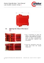
Страница 18: ...pro SV13_E doc Version 1 3 08 11 10 Page 18 of 20 12 Opening the LVCpro S Enclosure 1 Use a screwdriver to push the splint in the opening tab down located underneath the connector plugs of Power Piezz...

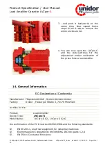
Страница 19: ...the adjustment and or calibration of the press force are accessible 14 General Information EC Declaration of Conformity Manufacturer TRsystems GmbH System Division Unidor Factory Unidor Freiburger Str...

Страница 20: ...e LVCpro S Copyright 2010 TRsystems GmbH Systembereich Unidor LVCpro SV13_E doc Version 1 3 08 11 10 Page 20 of 20 EN 55022 Radio Radiation VDE 0100 VDE 0113 EN 60204 Issued by TRsystems GmbH System D...

Отзывы: