background image

9

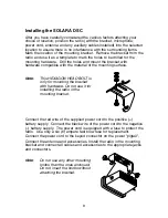
Installing the SOLARA DSC

After you have carefully considered the various factors affecting your
choice of location, position the radio (with the bracket, microphone,
power cord, antenna and any auxiliary cables installed) into the selected
location to assure there is no interference with the surrounding items.  
Mark the location of the mounting bracket.  Remove the bracket from the
radio and use it as a template to mark the holes to be drilled for the
mounting hardware.  Drill the holes and mount the bracket with
hardware compatible with the material of the mounting surface.

Note

:

This HEXAGON HEAD BOLT is
only for mounting the bracket
with hardware. Do not use it for
installing the radio in the
mounting bracket.

Connect the red wire of the supplied power cord to the positive (+)
battery supply.  Connect the black wire of the power cord to the negative
(–) battery supply.  The power cord is equipped with a fuse to protect the
radio.  Use only a six (6) ampere fast blow fuse for replacement.
Connect the power cord to the keyed connector on the power "pigtail".

Connect the antenna and accessories. Install the radio in the mounting
bracket and connect all cables and accessories to the appropriate jacks
and connectors.

Note

:

Do not use any other mounting
knobs than the ones enclosed.
Do not insert the knobs without
attaching the bracket.

Содержание DSC

Страница 1: ......

Страница 2: ...ntly for use in the U S without an individual license please contact the FCC Call Center at 1 888 CALL FCC Maritime Radio Services Operation Warning For individuals requiring a license such as commercial users you should obtain a license application from your nearest FCC field office Uniden works to reduce lead content in our PVC coated cords in our products and accessories WARNING The cords on th...

Страница 3: ...ecting a Channel 12 Weather Channels 12 All Channel Scan 13 Weather Alert 13 Setting the Transmit TX Power 14 Recommended Emergency Broadcast Instructions 15 Distress 16 Digital Selective Calling DSC 17 Individual 17 All Ships 18 User MMSI 20 NMEA Technical Setup 21 Optional Accessories 21 VHF FM Marine Radio Telephone Channel and Functions USA Channels 22 Channel and Functions International Chann...

Страница 4: ...ns in marine service The SOLARA DSC is of all solid state design with conservatively rated rugged components and materials compatible with the marine environment The transceiver utilizes a number of gaskets sealing rings waterproof membranes and other sealants to effect a waterproof housing for protection of the electronics It meets the most stringent JIS7 waterproof specification The unit may be ...

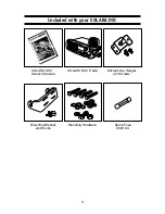
Страница 5: ...3 Included with your SOLARA DSC SOLARA DSC Owner s Manual SOLARA DSC Radio Microphone Hanger and Screws Mounting Bracket and Knobs Spare Fuse 250V 6A Mounting Hardware ...

Страница 6: ...key to change the transmit power to either High or Low Press and hold this key for 2 seconds to place the radio into the Scan mode Press both HI LO SCAN UIC and WX ALERT UIC at the same time to change channel modes from USA to INTERNATIONAL to CANADIAN 8 WX ALERT UIC Press this key to listen to active NOAA Weather channels Press and hold this key for 2 seconds to place the radio into the Weather A...

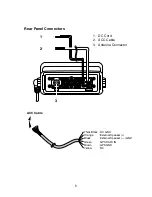
Страница 7: ...5 Rear Panel Connectors 3 1 ACC Cable 1 DC Cord 2 ACC Cable 3 Antenna Connector Thick Black DC GND Orange External Speaker Black External Speaker GND Green GPS DATA IN Brown GPS GND Yellow NC 2 ...

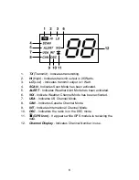
Страница 8: ...5 ALERT Indicates Weather Alert Mode has been activated 6 WX Indicate Weather Channel Mode has been activated 7 USA Indicates US Channel Mode 8 CAN Indicates Canada Channel Mode 9 INT Indicates International Channel Mode 10 DSC Indicators the radio is in the DSC mode 11 GPS Icon It appears while GPS module is receiving the data 12 Channel Display Indicates Channel Number in use ...

Страница 9: ... dash mounting using the optional bracket Choosing a Location Some important factors to consider in selecting the location for your SOLARA DSC 1 Select a location that is free from spray and splash 2 Keep the battery leads as short as possible Direct connection to the battery is most desirable If direct connection can not be made with the supplied power lead any extension should be made with 10 AW...

Страница 10: ...rements In general communication range is increased by using a high gain antenna placed as high as possible above the water line Antennas should be located away from metal objects Antennas should not have excessively long coaxial feed cables Antenna Selection and Installation SOLARA DSC has been designed to accomodate all of the popular marine VHF antennas However the selection and the installatio...

Страница 11: ...nting surface Note This HEXAGON HEAD BOLT is only for mounting the bracket with hardware Do not use it for installing the radio in the mounting bracket Connect the red wire of the supplied power cord to the positive battery supply Connect the black wire of the power cord to the negative battery supply The power cord is equipped with a fuse to protect the radio Use only a six 6 ampere fast blow fus...

Страница 12: ...dio for the first time after purchase the channel 16 will appear on the LCD Operation Last Channel Memory The SOLARA DSC memorizes the last channel selected before you turn Off the radio For example if you turn Off the radio on CH 12 the CH 12 will be on that channel when turned back On Note In order for the last channel to be memorized you must have the radio on that channel for 3 seconds ...

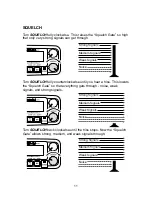
Страница 13: ...ss This lowers the Squelch Gate so that everything gets through noise weak signals and strong signals Turn SQUELCH back clockwise until the hiss stops Now the Squelch Gate allows strong medium and weak signals through Strong Signals Medium Signals Weak Signals Noise Strong Signals Medium Signals Weak Signals Noise Strong Signals Medium Signals Weak Signals Noise SQUELCH ...

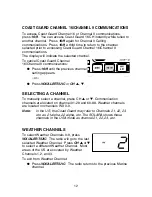
Страница 14: ... the US the Coast Guard may refer to Channels 21 22 23 etc as 21 alpha 22 alpha etc The SOLARA shows these channels in the USA mode as channel 21 22 23 etc COAST GUARD CHANNEL 16 CHANNEL 9 COMMUNICATIONS To access Coast Guard Channel 16 or Channel 9 communications press 16 9 You can access Coast Guard 16 CH instantly while tuned to another channel Press 16 9 again for Channel 9 Calling communicati...

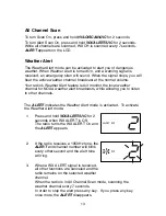
Страница 15: ...X ALERT UIC for 2 seconds While all channels are scanned WX CH is scanned every 7 seconds ALERT appears on the LCD 1 Press and hold WX ALERT UIC for 2 seconds when WX ALERT is Off The radio turns the WX ALERT On and the ALERT appears 2 If the radio receives a 1050Hz tone the ALERT and channel number will blink every other second and the alert tone will ring 3 When a WX ALERT signal is received all...

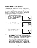
Страница 16: ...ations 1 When you turn the radio On for the first time the unit is automatically set to transmit at 25 watts HI 2 Press HI LO SCAN UIC to change the transmitter output to 1 watt LO 3 Press HI LO SCAN UIC again to change back to 25 watts HI Note A short tone sounds everytime you press the HI LO SCAN UIC CH13 is 1 watt LO channel When the channel is LO power channel you can transmit at 25 watts HI b...

Страница 17: ...o acknowledgement or if the Coast Guard or another vessel responds say MAYDAY or PAN INSERT VESSEL S NAME 7 DESCRIBE YOUR POSITION using latitude and Longitude coordinates LORAN coordinates or range and bearing from a known point 8 STATE THE NATURE OF THE DISTRESS 9 GIVE NUMBER OF PERSONS ABOARD AND THE NATURE OF ANY INJURIES 10 ESTIMATE THE PRESENT SEA WORTHINESS OF YOUR VESSEL 11 BRIEFLY DESCRIB...

Страница 18: ...it waits for about 210 270 seconds for an acknowledgement from the Coast Guard before the Distress call is resent After the Distress call has been sent the Distress alert will sound every other second The radio will automatically change to channel 16 and it also watches channel 70 in the background until an acknowledgement signal is received from the Coast Guard shore station To cancel the Distres...

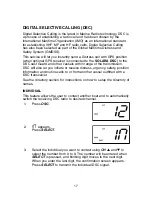
Страница 19: ...F MF and HF radio calls Digital Selective Calling has also been selected as part of the Global Maritime Distress and Safety System GMDSS This service will let you instantly send a Distress call with GPS position when optional GPS receiver is connected to the SOLARA DSC to the US Coast Guard and other vessels within range of the transmission DSC will also let you initiate or receive distress urgenc...

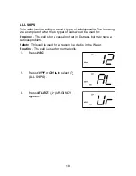
Страница 20: ... these types of calls would be used for Urgency This call is for a vessel not yet in Distress but may have a serious problem Safety This call is used for a reason like debris in the Water Routine This call is used for normal calls 1 Press DSC 2 Press CH or CH to select ALL SHIPS 3 Press SELECT URGENCY appears ...

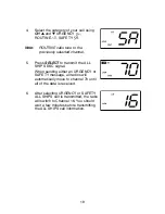
Страница 21: ...o transmit the ALL SHIPS DSC signal When sending either an URGENCY or SAFETY message all radios will automatically move to channel 70 until all of the data is received 6 After selecting URGENCY or SAFETY ALL SHIPS call is transmitted the radio will switch to Channel 16 You should wait a few minutes before transmitting the ALL SHIPS call information ...

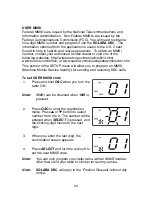
Страница 22: ...gsafety mmsiinfo htm This portion of the SETUP menu will allow you to program an MMSI Maritime Mobile Service Identity for sending and receiving DSC calls To set USER MMSI code 1 Press and hold DSC when you turn the radio ON Note MMSI can be checked when 16 9 is pressed 2 Press DSC to enter the registration mode Press or button to select number from 0 to 9 The number will be entered when SELECT is...

Страница 23: ...tput This output can be used to supply information to other devices on the vessel such as the SOLARA DSC VHF radio auto pilots chart plotters etc To setup the GPS to be used with the SOLARA DSC radio the following items need to be considered for proper operation 1 Baud Rate Set the Baud rate to 4800 2 Data Bits Set the Data Bits to 8 3 Parity Set the Parity to None 4 Stop Bits Set the Stop Bits to...

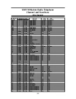
Страница 24: ... 156 950 Com l Yes Yes 20 157 000 157 000 Port Ops RX Duplex Yes Yes 21 157 050 157 050 Coast Guard Yes Yes 22 157 100 157 100 Coast Guard Yes Yes 23 157 150 157 150 Coast Guard Yes Yes 24 157 200 161 800 Public Corresp Duplex No Yes 25 157 250 161 850 Public Corresp Duplex No Yes 26 157 300 161 900 Public Corresp Duplex No Yes 27 157 350 161 950 Public Corresp Duplex No Yes 28 157 400 162 000 Pub...

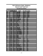
Страница 25: ...6 950 161 550 Com l Duplex Yes Yes 20 157 000 161 600 Port Ops Duplex Yes Yes 21 157 050 161 650 Coast Guard Duplex Yes Yes 22 157 100 161 700 Coast Guard Duplex Yes Yes 23 157 150 161 750 Coast Guard Duplex Yes Yes 24 157 200 161 800 Public Corresp Duplex No Yes 25 157 250 161 850 Public Corresp Duplex No Yes 26 157 300 161 900 Public Corresp Duplex No Yes 27 157 350 161 950 Public Corresp Duplex...

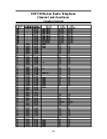
Страница 26: ...0 156 700 Yes Yes 15 156 750 156 750 1W Yes Yes 16 156 800 156 800 Yes Yes 17 156 850 156 850 1W Yes Yes 18 156 900 156 900 Yes Yes 19 156 950 156 950 Yes Yes 20 157 000 161 600 Duplex 1W Yes Yes 21 157 050 157 050 Yes Yes 22 157 100 157 100 Yes Yes 23 157 150 161 750 Duplex Yes Yes 24 157 200 161 800 Duplex No Yes 25 157 250 161 850 Duplex No Yes 26 157 300 161 900 Duplex No Yes 27 157 350 161 95...

Страница 27: ... FCC Approvals Type accepted under part 80 of the Rules meets Great Lakes Agreement and party boat requirements Transmitter Power Output 1 watt or 25 watt switch selectable Power Requirement Not rated on LO 25 watts output 5 3A 13 8V DC Modulation FM 5 kHz deviation FCC designator F3E Hum and Noise Signal to Noise 45 dB 1 kHz with 3 kHz deviation with 1000 Hz modulating frequency nominal Audio Dis...

Страница 28: ...noise is being generated by some device SYMPTOM Won t power On When the PTT is pressed Tx comes on and another radio can hear a click but no audio is heard While scanning the radio stops on a particular channel all of the time There is noise on the receiver that the squelch will not eliminate REMEDY Check for proper voltage getting to the set Send in for repair Eliminate the source of the noise or...

Страница 29: ...r a few precautions should be observed If the antenna has been damaged you should not transmit except in the case of an emergency A defective antenna may cause damage to your radio You are responsible for continued FCC technical compliance of your radio You are urged to arrange for periodic performance checks with your Uniden Marine dealer Care and Maintenance ...

Страница 30: ...28 Note ...

Страница 31: ...ntor or its representatives in connection with the performance of this warranty THE LIMITED WARRANTY SET FORTH ABOVE IS THE SOLE AND ENTIRE WARRANTY PERTAINING TO THE PRODUCT AND IS IN LIEU OF AND EXCLUDES ALL OTHER WARRANTIES OF ANY NATURE WHATSOEVER WHETHER EXPRESS IMPLIED OR ARISING BY OPERATION OF LAW INCLUDING BUT NOT LIMITED TO ANY IMPLIED WARRANTIES OF MERCHANTABILITY OR FITNESS FOR A PARTI...

Страница 32: ...UTZZ01600ZZ ...

Отзывы: