
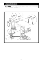
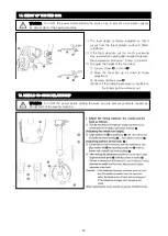
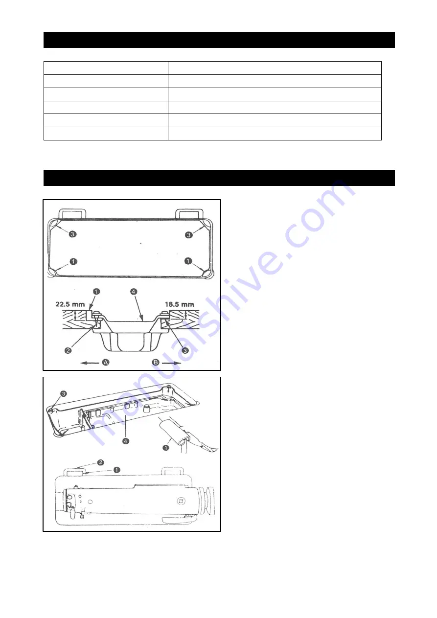
1
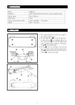
1)
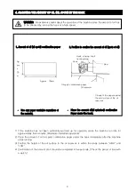
The oil pan should rest on the four corners of
the machine table groove.
2)
Fix two rubber seats
➊
on side
Ⓐ
(operator’
s side) using nails
➋
as illustrated above. Fix
two cushion seats
➌
on side
Ⓑ
(hinged side)
using a rubber-based adhesive. Then place
oil pan
➍
on the fixed seats.
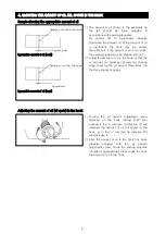
3)
Fit hinge
➊
into the opening in the machine
bed, and fit the machine head to table rubber
hinge
➋
before placing the machine head on
cushions
➌
on the four corners.
Model
H5600-D
Application
Light-weight materials and medium-heavy weight materials
Sewing speed
Max. 4,500 rpm
Stitch length
4 mm
Presser foot lift (by knee lifter)
4.5mm (standard) 13mm (max.)
Needle
DB x 1 #9~#18
1. SPECIFICATIONS
2. INSTALLATION
Содержание H5600-D
Страница 1: ......
Страница 16: ...12 19 ATTACHING THE CLOTH CUTTING KNIFE 20 CHANGING THE CUTTING WIDTH...
Страница 17: ...13 21 ADJUSTING THE KNIFE COMPONENTS 22 ADJUSTING THE HEIGHT OF THE KNEE LIFTER...
Страница 18: ...14 23 OTHER REPLACEMENT PARTS...
Страница 19: ...15 24 WINDING THE LOWER THREAD 25 INSTALLING THE THREAD STAND...
Страница 20: ...16 26 ATTACHING THE WASTE CLOTH GUIDE...
Страница 21: ......
Страница 22: ...1 1 Machine Frame Miscellaneous Cover Mechanism 1...
Страница 24: ...3 1 Machine Frame Miscellaneous Cover Mechanism 2...
Страница 26: ...5 2 Main Shaft Thread Take up Lever Mechanism 1...
Страница 28: ...7 2 Main Shaft Thread Take up Lever Mechanism 2...
Страница 30: ...9 3 Needle Bar Vertical Shaft Hook Driving Shaft Mechanism...
Страница 32: ...11 4 Hand Lifter Mechanism...
Страница 34: ...13 5 Feed Mechanism 1...
Страница 36: ...15 5 Feed Mechanism 2...
Страница 38: ...17 6 Thread Trimmer Mechanism...
Страница 40: ...19 7 Automatic Reverse Feed Mechanism...
Страница 42: ...21 8 Oil Lubrication Mechanism Bobbin Mechanism...
Страница 44: ...23 9 Oil Pan Mechanism...
Страница 49: ......


