background image


IMPORTANT SAFETY INSTRUCTIONS 


Putting sewing systems into operation is prohibited until it has been ascertained that the sewing systems 
in  which  these  sewing  machines  will  be  built  into,  have  conformed  with  the  safety  regulations  in  your 
country. Technical service for those sewing systems is also prohibited. 

9.


Tampering  with  the  live  parts  and  devices,  regardless  of  whether  the  machine  is  powered,  is 
prohibited. 

10.


Repair, remodeling and adjustment works must only be done by appropriately trained technicians or 
specially skilled personnel. 

11.


General maintenance and inspection works have to be done by appropriately trained personnel. 

12.


Repair  and  maintenance  works  of  electrical  components  shall  be  conducted  by  qualified  electric 
technicians or under the audit and guidance of specially skilled personnel. 
Whenever you find a failure of any of electrical components, immediately stop the machine. 

13.


Before making  repair and  maintenance works  on the machine equipped with pneumatic parts such 
as an air cylinder, the air compressor has to be detached from the machine and the compressed air 
supply has to be cut off. Existing residual air pressure after disconnecting the air compressor from the 
machine has to be expelled. Exceptions to this are only adjustments and performance checks done 
by appropriately trained technicians or specially skilled personnel. 


1.


Observe the basic safety measures, including, but not limited to the following ones, whenever you use 
the machine. 

2.


Read  all  the  instructions,  including,  but  not  limited  to  this  Instruction  Manual  before  you  use  the 
machine. 
In addition, keep this Instruction Manual so that you may read it at anytime when necessary. 

3.


Use  the  machine  after  is  has  been  ascertained  that  it  conforms  with  safety  rules/standards  valid  in 
your country. 

4.


All safety devices must be in position when the machine is ready for work or in operation. 
The operation without the specified safety devices is not allowed. 

5.


This machine shall be operated by appropriately-trained operators. 

6.


For  the  following,  turn  off  the  power  switch  or  disconnect  the  power  plug  of  the  machine  from  the 
receptacle. 
6-1 For threading needle(s), looper, spreader etc. and replacing bobbin. 
6-2 For replacing part(s) of needle, presser foot, throat plate, looper, spreader, feed dog, needle   
      guard, folder, cloth guide etc. 
6-3 For repair work. 
6-4 When leaving the working place or when the working place is unattended. 
6-5  When  using  clutch  motors  without  applying  brake,  it  has  to  be  waited  until  the  motor  stopped 
totally. 

7.


If you should allow oil, grease, etc. used with the machine and devices to come in contact with your 


17.


The machine is only allowed to be used for the purpose intended. Other used are not allowed. 

18.


Remodel  or  modify  the  machine  in  accordance  with  the  safety  rules/standards  while  taking  all  the 
effective safety measures. UNICORN assumes no responsibility for damage caused by remodeling or 
modification of the machine. 

15.


Grounding the machine is  always necessary for the  normal  operation  of the machine. The machine 
has to be operated in an environment that is free from strong noise sources such as high-frequency 
welder. 

16.


An  appropriate  power  plug  has  to  be  attached  to  the  machine  by  electric  technicians.  Power  plug 


19.


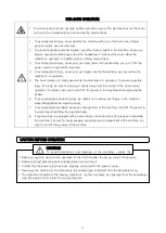
Warning hints are marked with the two shown symbols. 
 
                  Danger of injury to operator or service staff 
 
                  Items requiring special attention.


Содержание H5600-D

Страница 1: ......

Страница 2: ...addition keep this Instruction Manual so that you may read it at anytime when necessary 3 Use the machine after is has been ascertained that it conforms with safety rules standards valid in your count...

Страница 3: ...In addition be sure to turn OFF the power to the machine when replacing the bobbin 6 To avoid possible personal injuries be careful not to allow your fingers in the machine when tilting raising the ma...

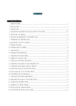
Страница 4: ...SSER FOOT PRESSURE 9 13 ADJUSTING THE FEED TIMING 9 14 HEIGHT OF THE FEED DOG 10 15 NEEDLE TO HOOK RELATIONSHIP 10 16 ADJUSTING THE HEIGHT OF THE PRESSER FOOT 11 17 ADJUSTING THE THREAD TAKE UP STROKE...

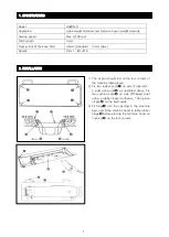
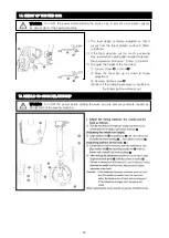
Страница 5: ...n place oil pan on the fixed seats 3 Fit hinge into the opening in the machine bed and fit the machine head to table rubber hinge before placing the machine head on cushions on the four corners Model...

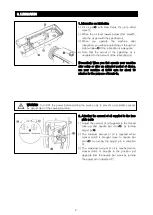
Страница 6: ...disuse run your machine at 3 000 spm for about 10 minutes for the purpose of break in 2 Adjusting the amount of oil supplied to the face plate parts 1 Adjust the amount of oil supplied to the thread t...

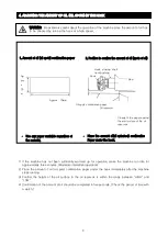
Страница 7: ...e seconds Check the period of time with a watch 4 ADJUSTING THE AMOUNT OF OIL OIL SPOTS IN THE HOOK WARNING Be extremely careful about the operation of the machine since the amount of oil has to be ch...

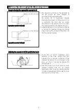
Страница 8: ...the appropriate amount of oil Adjusting the amount of oil oil spots in the hook 1 Turning the oil amount adjustment screw attached on the hook driving shaft front bushing in the direction in direction...

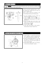
Страница 9: ...of hole is reached 4 Securely tighten screw 5 Check that long groove of the needle is facing exactly to the left in direction 1 Hold the bobbin in a way that the thread open end is directed to the lef...

Страница 10: ...6 7 THREADING THE MACHINE HEAD WARNING Turn OFF the power before starting the work so as to prevent a accidents caused by abrupt start of the sewing machine...

Страница 11: ...e sewing specifi cations 2 As you turn nut clockwise in direction the needle thread tension will increase 3 As you turn nut counterclockwise in direction the needle thread tension will derease 2 Adjus...

Страница 12: ...setscrew 3 As you turn tension post clockwise in direction the pressure will be increased 4 As you turn the post counterclockwise in direction the pressure will be decreased 1 To stop the machine wit...

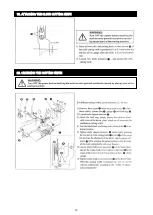
Страница 13: ...e top end of needle eyelet are flush with the top surface of throat plate when the feed dog descends below the throat plate 3 To advance the feed timing in order to prevent uneven material feed move t...

Страница 14: ...en screw of crank Move the feed bar up or down to make adjustment Securely tighten screw Caution If the clamping pressure is insufficient the forked portion will wear out WARNING Turn OFF the power be...

Страница 15: ...11 17 ADJUST THE THREAD TAKE UP STROKE 16 ADJUST THE HEIGHT OF THE PRESSER FOOT 17 ADJUST THE THREAD TAKE UP STROKE 18 OPERATION OF THE CLOTH CUTTING KNIFE...

Страница 16: ...12 19 ATTACHING THE CLOTH CUTTING KNIFE 20 CHANGING THE CUTTING WIDTH...

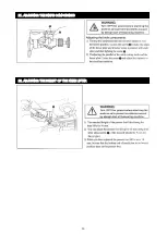
Страница 17: ...13 21 ADJUSTING THE KNIFE COMPONENTS 22 ADJUSTING THE HEIGHT OF THE KNEE LIFTER...

Страница 18: ...14 23 OTHER REPLACEMENT PARTS...

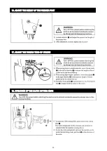
Страница 19: ...15 24 WINDING THE LOWER THREAD 25 INSTALLING THE THREAD STAND...

Страница 20: ...16 26 ATTACHING THE WASTE CLOTH GUIDE...

Страница 21: ......

Страница 22: ...1 1 Machine Frame Miscellaneous Cover Mechanism 1...

Страница 23: ...ber Plug 1 17 01 017 Screw 1 18 01 018 Reverse Feed Lever Stopper 1 19 01 019 Rubber Plug 1 20 01 020 Rubber Plug 1 21 01 021 Thread Tension Asm 1 22 01 022 Thread Tension Post 1 23 01 023 Thread Tens...

Страница 24: ...3 1 Machine Frame Miscellaneous Cover Mechanism 2...

Страница 25: ...Plug 2 50 01 050 Screw 3 51 01 051 Slide Plate Asm 1 52 01 052 Slide Plate 1 53 01 053 Bed Slide Spring 1 54 01 054 Screw 2 55 01 055 Bed Screw Stud 4 56 01 056 Down Plate 1 57 01 057 Machine Head As...

Страница 26: ...5 2 Main Shaft Thread Take up Lever Mechanism 1...

Страница 27: ...Screw 2 18 02 018 Feed Drive Eccentric Cam 1 19 02 019 Screw 2 20 02 020 Bearing 1 21 02 021 Oil Seal 1 22 02 022 Snap Ring 1 23 02 023 Collar 1 24 02 024 1 25 02 025 Main Shaft Front Bushing 1 26 02...

Страница 28: ...7 2 Main Shaft Thread Take up Lever Mechanism 2...

Страница 29: ...crew 3 47 02 047 Friction Gear 1 48 02 048 Linker 2 1 49 02 049 Screw M6X0 75 3 50 02 050 Crank Slide Block 1 51 02 051 Knife Driving Stud Connection Asm 1 52 02 052 Screw 1 53 02 053 Knife Cam Screw...

Страница 30: ...9 3 Needle Bar Vertical Shaft Hook Driving Shaft Mechanism...

Страница 31: ...3 014 Conical Gear 1 15 03 015 Screw 8 16 03 016 Conical Gear 1 17 03 017 Screw 1 18 03 018 Bushing Intermediate 1 19 03 019 Gear 1 20 03 020 Screw 1 21 03 021 Conical Gear 1 22 03 022 Oil Wick 1 23 0...

Страница 32: ...11 4 Hand Lifter Mechanism...

Страница 33: ...1 18 04 018 Wire Holder 2 19 04 019 Screw 1 20 04 020 Wire Holder Bracket Upper 1 21 04 021 Nut 2 22 04 022 Screw 1 23 04 023 Tension Release Return Spring 1 24 04 024 Thread Release Pin Spring 1 25...

Страница 34: ...13 5 Feed Mechanism 1...

Страница 35: ...20 05 020 Screw 1 21 05 021 Knife Holder 1 22 05 022 Spring 1 23 05 023 Screw 1 24 05 024 Walking Foot Short Pin 2 25 05 025 Connecting Link Long Pin 2 26 05 026 Connecting Link Short Pin 2 27 05 027...

Страница 36: ...15 5 Feed Mechanism 2...

Страница 37: ...05 065 Feed Lever Bushing 1 66 05 066 Screw 1 67 05 067 Screw 1 68 05 068 Reverse Feed Control Lever 1 69 05 069 Holder 1 70 05 070 Screw 2 71 05 071 Throat Plate 1 72 05 072 Screw 2 73 05 073 Waste...

Страница 38: ...17 6 Thread Trimmer Mechanism...

Страница 39: ...1 24 06 024 Thread Shear Cam Bushing 1 25 06 025 Screw 1 26 1 06 026 01 Thread Shear Rock ARM Shaft 1 26 2 06 026 02 Slippery Piece Shaft Asm 1 26 3 06 026 03 Slide Block Shaft 1 26 4 06 026 04 Slide...

Страница 40: ...19 7 Automatic Reverse Feed Mechanism...

Страница 41: ...07 009 Plunger Arm Pin 1 10 07 010 Reverse Feed Magnet Asm 1 11 07 011 Plunger Spring 1 12 07 012 Pin Contact 2 13 07 013 Screw 15 64X28 L 12 2 14 07 014 Washer 2 15 07 015 Spring Washer 2 16 07 016 E...

Страница 42: ...21 8 Oil Lubrication Mechanism Bobbin Mechanism...

Страница 43: ...cating Oil Pump Cover 1 18 08 018 Oil Pump Impeller Cover 1 19 08 019 Plunger 1 20 08 020 Plunger Spring 1 21 08 021 Plunger Screw 1 22 08 022 Hook Driving Shaft Oil Tube 1 23 08 023 Screw 3 24 08 024...

Страница 44: ...23 9 Oil Pan Mechanism...

Страница 45: ...11 09 011 Screw 2 12 09 012 Nut 2 13 09 013 Screw 2 14 09 014 Screw 1 15 09 015 Knee Press Cross Shaft 1 17 09 017 Knee Pan Plate Cover 1 18 09 018 Knee Pan Upright Shaft 1 19 09 019 Knee Pan Plate R...

Страница 46: ...10 007 Thread Guide Arm Joint 2 8 10 008 Spool Rest Rod Rubber Cap 1 9 10 009 Spool Rest Arm 2 10 10 010 Spool Rest Rod Upper 1 11 10 011 Spool Rest Rod Joint 1 12 10 012 Screw 2 13 10 013 Nut 2 14 10...

Страница 47: ...8 11 008 Head Cover 1 9 11 009 Rest 1 10 11 010 Oil Reservoir Asm 1 11 11 011 Needle 5 12 11 012 1 13 11 013 Wrench 1 14 11 014 1 15 11 015 Instruction Manual Parts Book 1 16 11 016 Cover Component 1...

Страница 48: ...ion Q ty 1 12 001 Motor Cover 1 2 12 002 Screw 4 3 12 003 Motor Ass 1 4 12 004 Screw 4 5 12 005 Spring Washer 4 6 12 006 Panel Setting Plate 1 7 12 007 Control Box 1 8 12 008 Shaft Plate 4 9 12 009 Wa...

Страница 49: ......
Отзывы: