UC-00-M31 EN P1.0.0
Packaging
17
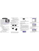
Figure 5-2 UM982 Package
0.10
21.80± 0.10
3.30± 0.10
16.80± 0.10
24.00± 0.10
0.00
1.50 ±
0.35± 0.05
C
P2
P0
B
B-B
B
Dimensions
B0
K0
10Po
P
Ao
W
Po
Do
44.00± 0.30
40.00± 0.20
4.00± 0.10
E
S
P2
F
1.75± 0.10
40.40± 0.10
2.00± 0.10
t
1.
70
+0
.15
-0
.05
1.50
+0.10
-0.00
C(3:1)
20.20± 0.10
Cover Tape
Carrier
Tape
Feed Direction
Reel
D1
A
W
S
F
E
330*100*44
A-A
A
24
3.
3
0.
3
21
.8
0.35
16.8
R
ee
l P
ac
ka
gin
g D
ia
gr
am
(F
or
R
ef
ere
nc
e O
nly
)
Note:
1.
The cumulative tolerance of 10 side holes should not exceed ± 0.2 mm.
2.
Material: Black antistatic PS (surface impedance 10
5
-10
11
) (surface static
voltage <100 V), thickness: 0.35 mm.
3.
Total length of the 13-inch reel package: 6.816 m (Length of the first part of
empty packets: 0.408 m, length of packets containing modules: 6 m, length
of the last part of empty packets: 0.408 m).
4.
Total number of packets in the 13-inch reel package: 284 (Number of the
first part of empty packets: 17; actual number of modules in the packets:
250; number of the last part of empty packets: 17).
5.
All dimension designs are in accordance with EIA-481-C-2003.
6.
The maximum bending degree of the carrier tape within the length of 250
mm should not exceed 1 mm (see the figure below).


