UM220 User Manual
6
3
Technical Specifications
3.1
Electrical Specifications
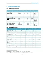
Absolute Maximum Ratings
Item
Pin
Min
Max
Unit
Description
Power Supply (VCC)
Vcc
-0.5
3.6
V
Main power
Backup Voltage
V_BCKP
-0.5
3.6
V
Backup
power
supply for
RTC
Digital IO (RXD1
,
RXD2)
4
Vin
-0.5
3.6
VV
VCC
Ripple (Rated Max.)
Vrpp
0
50
mVpp
RF_IN
RF_IN
-
+3
dBm
Max input
power of
antenna
Storage Temperature
Tstg
-45
90
°C
SMT Reflow Temperature
T
SLDR
-
+260
°C
Maximum ESD stress
VESD(HBM)
2000
V
All
pins,HBM
3.2
Operation Condition
Item
Pin
Min.
Typical
Value
Max.
Unit
Condition
Power Supply (VCC)
Vcc
2.8
3.3
3.6
V
Ripple Voltage
Vp-p
50
mV
Peak current
Iccp
54
mA
Vcc = 3.0 V
Tracking average
current
I
ACQ
27
31
34
mA
Vcc = 3.0V
LOW Level Input
Voltage
V
IL
-0.3
0.2*Vcc
V
High Level Input
Voltage
V
IH
0.7*Vcc
Vcc+0.3
V
LOW Level Output
Voltage
V
OL
0
0.4
V
Iout = -2 mA
High Level Output
Voltage
V
OH
Vcc–0.4
Vcc
V
Iout = 2 mA
Antenna Gain
5
G
ANT
15
20
30
dB
Noise Figure
NF
1.5
dB
Operating
Temperature
T
OPR
-40
85
°C
4
Including
nRESET,TIMEPULSE,WHEELTICK,TXD2,RXD2,FWD,TXD1,RXD1
5
The antenna gain range refers to the gain range of the preamplifier before RF_IN of the module.


