UM980eb User Manual
ii
Should you purchase our product and encounter any inconsistency, please contact us or
our local authorized distributor for the most up-to-date version of this manual along
with any addenda or corrigenda.
Страница 1: ...HARDWARE USER MANUAL WWW UNICORECOMM COM Copyright 2009 2023 Unicore Communications Inc Data subject to change without notice UM980eb Evaluation Board...
Страница 2: ...serial referred to in this manual collectively Unicore Trademarks This manual or any part of it shall not be deemed as either expressly implied by estoppel or any other form the granting or transferr...
Страница 3: ...Manual ii Should you purchase our product and encounter any inconsistency please contact us or our local authorized distributor for the most up to date version of this manual along with any addenda o...
Страница 4: ...i Foreword This manual provides information on the hardware composition and design of UM980eb evaluation board Target Readers This document is written for technicians who are familiar with GNSS module...
Страница 5: ...4 3 Power Supply 6 3 1 3 3V LDO Power Supply 7 3 2 5V DC DC Power Supply 8 3 3 Backup Power Supply 9 4 Antenna Circuit 10 4 1 Antenna Detection Circuit 10 4 2 Antenna Feed Circuit 12 5 LED Indicators...
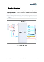
Страница 6: ...O a 5V DC DC boost circuit an antenna detection circuit and peripheral interfaces The schematic of the UM980eb can be used as the reference design for the UM980 module UM980eb UM980 ANT_IN VBCKP PPS C...
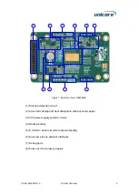
Страница 7: ...socket The printing adopts exposed copper to ensure the flatness of the surface 2 UM980 module The pin pads are designed long which is convenient for soldering testing and debugging For detailed packa...
Страница 8: ...UM980eb 1 Antenna detection circuit 2 Anti static design and heat dissipation with exposed copper 3 VCC power supply and LDO circuit 4 Backup battery 5 5 V DC DC boost circuit for antenna feeding 6 D...
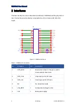
Страница 9: ...J18 on Unicore HPL EVK V5 0 board J4 CH71283V100 Figure 2 1 UM980eb Interfaces Table 2 1 UM980eb Pin Description No Pin Name I O Description 1 SPIS_MOSI I Master Out Slave In This pin is used to rece...
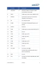
Страница 10: ...nnection inside 11 EVENT I Event input with adjustable frequency and polarity 12 RSV 22 Reserved 13 TXD3 O COM3 output can be used as CAN TXD LVTTL 14 GND Ground 15 TXD1 O COM1 output LVTTL 16 RXD1 I...
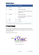
Страница 11: ...evel when passing self test 27 SDA I O I2 C data 28 SCL I O I2 C clock The availability of the ports depends on the firmware version of the UM980 module 3 Power Supply The power supply of the UM980eb...
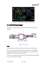
Страница 12: ...101DRB Figure 3 3 3 3V LDO Circuit Notes The rated output current of LDO should be more than twice the current of UM980 R38 is a series resistor placed at the input of the LDO which is used for debugg...
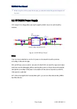
Страница 13: ...5V DC DC Boost Circuit Notes You can choose whether to use the 5 V power on the board to feed the antenna according to the antenna type R61 and R76 are series resistors connected to the DC DC circuit...
Страница 14: ...uit should be designed to prevent reverse current to ensure that the battery only supplies power to V_BCKP and the current does not flow back into the 3 3 V power domain as the D52 shows in Figure 3 5...
Страница 15: ...o battery runs out of power it will take more than 96 hours to fully charge the battery 4 Under normal circumstances after powering the evaluation board for one night the hot start test can be done no...
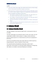
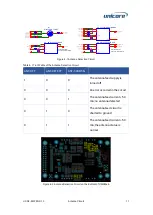
Страница 16: ...Detection Circuit Table 4 1 Truth Table of the Antenna Detection Circuit ANT OFF ANT DETECT ANT SHORT N 1 X X The antenna feed supply is turned off 0 0 0 An error occurred in the circuit 0 0 1 The an...
Страница 17: ...tection The supply voltage can be selected from 5 V VCC_RF or ANT_BIAS3 through R31 R29 R30 When using the 5 V voltage or VCC_RF the antenna detection circuit on UM980eb will be bypassed The ESD prote...
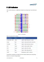
Страница 18: ...on Power 5V or 3 3V Green Light on when the power is normal Reset Red Light on when pressing the reset button Antenna Red Light on when antenna is shorted PVT Green Light on when position is fixed RTK...
Страница 19: ...with a total capacitance greater than 30 uF Add series resistors at the IO pins for the convenience of debugging VCCIN powers the UM980 module only R33 is a large size resistor with high rated power...
Страница 20: ...entify the resistors which is convenient for measurement Figure 6 2 UM980 Peripheral Circuit The GND pads at the bottom of the module should be grounded to ensure heat dissipation The UM980eb has copp...
Страница 21: ...rent TP2 TP3 TP5 and TP7 are used for internal debugging of which TP5 and TP7 can be used to debug I2C J1 is used for MMCX connection After soldering the MMCX connector it can be used to measure the P...
Страница 22: ...ug3 J1 NC Figure 7 1 Debug Ports for the UM980 Module The silkscreen markings on the right of the test points are arranged in order to identify the function of each port Figure 7 2 Through Hole Test P...
Страница 23: ...y 21 2022 Unicore Communications Inc R59 NC R74 0 C18 10uF J2 NC 1 2 R25 1k X4 NC J3 NC 1 2 FC1 NFM21PC104R1E3D 1 1 2 2 3 3 D7 19 21SYGC S530 E2 TR8 R11 5 1k J6 NC 1 2 R77 NC D9 19 21SYGC S530 E2 TR8...
Страница 24: ...itle Size Document Number Rev Date Sheet o f UM980 Module Ant Bias Debug Interface V1 0 UM980eb B 4 5 Friday January 21 2022 Unicore Communications Inc R10 0 D26 R67 33 D20 MBR120LSFT1G J5 1 2 3 4 5 R...
Страница 25: ...Assembly Top of UM980eb...
Страница 26: ...UM980eb User Manual Assembly Bottom of UM980eb...
Страница 27: ...Unicore Communications Inc 7 F3 No 7 Fengxian East Road Haidian Beijing P R China 100094 www unicorecomm com Phone 86 10 69939800 Fax 86 10 69939888 info unicorecomm com www unicorecomm com...