


UC-08-M32 EN R1.0
Interfaces
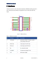
5
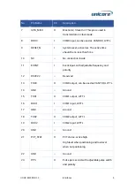
No.
Pin Name
I/O
Description
7
SPIS_MISO
O
Master In / Slave Out. This pin is used to
transmit data in slave mode.
8
RXD3
I
COM3 input, can be used as CAN RXD, LVTTL
9
RESET_N
I
System reset, active low.
The active time
should be no less than 5 ms.
10
NC
—
No connection inside
11
EVENT
I
Event input,
with adjustable frequency and
polarity
12
RSV#22
—
Reserved
13
TXD3
O
COM3 output, can be used as CAN TXD, LVTTL
14
GND
—
Ground
15
TXD1
O
COM1 output, LVTTL
16
RXD1
I
COM1 input, LVTTL
17
GND
—
Ground
18
TXD2
O
COM2 output, LVTTL
19
RXD2
I
COM2 input, LVTTL
20
GND
—
Ground
21
PVT_STAT
O
PVT status, active high.
High level when positioning and low level
when not positioning.
22
GND
—
Ground
23
PPS
O
Pulse per second, with adjustable pulse width
and polarity
Содержание UM980eb
Страница 25: ...Assembly Top of UM980eb...
Страница 26: ...UM980eb User Manual Assembly Bottom of UM980eb...