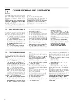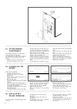
20
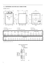
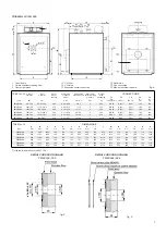
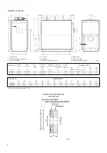
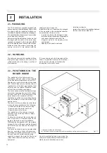
Electrical cables positioning
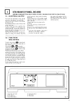
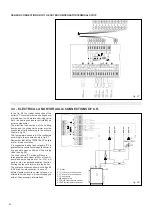
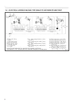
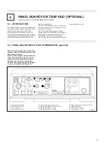
The panel board Standard or with outer
compensator) is equipped with a burner cable,
a PG 11 gland (pos. 2) and a 7 pole plug
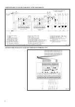
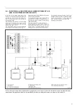
(pos. 3) - See wiring diagrams on figs. 24,
26, 31 and 33.
When fitting the panel board the leads of the
burner cable, which has to be passed through
the cable gland, must be connected to the
panel board terminal strip (see wiring diagrams
on figs. 24, 26, 31 & 33.
The seven pole plug and the cable must come
out from the casing through the cable clamp
plate (pos. 1), onto which the cable glande
must be fixed.
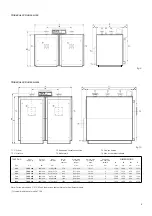
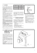
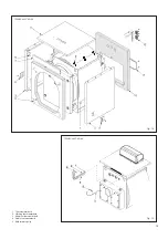
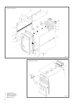
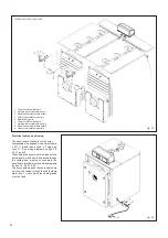
fig. 22
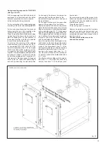
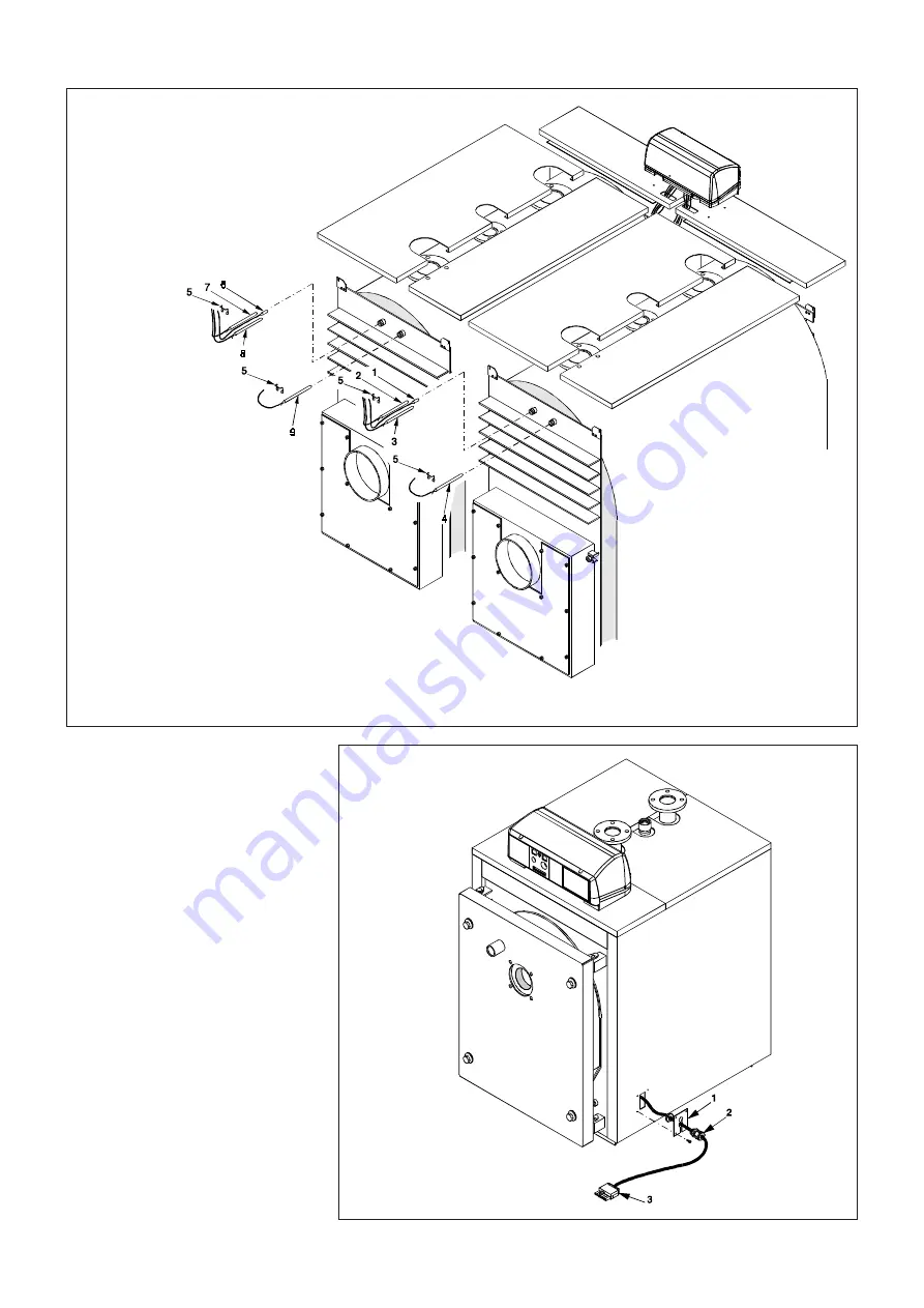
TRISECAL 3P DUO 360÷1200
fig. 21
1
Thermometer bulb boiler 1
2
Working thermostat bulb boiler 1
3
Minimum thermostat bulb boiler 1
4
Safety thermostat bulb boiler 1
5
Bulb retaining clip
6
Thermometer bulb boiler 2
7
Working thermostat bulb boiler 2
8
Minimum thermostat bulb boiler 2
9
Safety thermostat bulb boiler 2

