background image

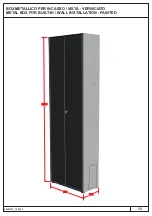
This unit makes it possible to install parts of the integrated system in indoor or outdoor walls.

t the bottom right, there

to pass the pipes through for the connection to the hydraulic system, to the electrical line

A

is opening

etc

At the top there

required to pass the pipes through for the connection to the solar system

is opening

.

Descrizione / Description:

Dimensioni / Dimensions:

L'unità da incasso permette l’installazione dei componenti del sistema integrato in pareti esterne o interne.
Essa è dotata nella parte inferiore destra di apertura necessaria per il passaggio dei tubi di allacciamento all'impianto idrico, alla linea elettrica etc.
Nella zona superiore vi sono i fori necessari per il passaggio dei tubi di allacciamento all'impianto solare.

A

350

20

20

7 0

0

350

90

29

40

23

28

141

R.PDC

C

F

M.PDC

R.Z

)

2 (mix

M.Z

)

2 (mix

R.Z1

M 1

.Z

7 0

0

2/8

Indicazioni relative ad attacchi per sistema SLIM - SLIMs HP 2.0
Hydraulic connection SLIM - SLIMs HP 2.0

C

F

Mi

Ri

R

M

pdc

R

pdc

Indicazioni relative ad attacchi per sistema / Hydraulic
connection HYBREER SLIM - SLIMs

Configurazione
Parallelo

(per configurazione
Serie vedere
libretto 00339318
pag. 7-8).

Configuration
Parallel

(for configuration
Series see
booklet 00339318
page 7-8).

Содержание SLIM HP 2.0

Страница 1: ...METAL BOX FOR BUILT IN WALL INSTALLATION PAINTED 00338775_ _202 12 3 1 8 BOX METALLICO PER INCASSO VISTA VERNICIATO 700 350 2200...

Страница 2: ...te inferiore destra di apertura necessaria per il passaggio dei tubi di allacciamento all impianto idrico alla linea elettrica etc Nella zona superiore vi sono i fori necessari per il passaggio dei tu...

Страница 3: ...e 2 and to the lh side 5 using the 4 supplied screws 3 5 2 3 3 3 1 4 3 8 Composizione L unit si compone di n 1 collo Coperchio superiore Fondo Fianco Sx Fianco Dx Schienale posteriore DX Schienale pos...

Страница 4: ...e back 5 and the back panel 6 to the perimeter using the supplied screws 3 LEFT RIGHT 6 5 3 4 8 Ruotare di 180 il perimetrale dell unit Fissare lo schienale SINISTRO 5 e lo schienale DESTRO 6 al perim...

Страница 5: ...th thermal acoustic insulation on the rear part of the supporting area a Built in installation Bracket clamps 5 8 Predisporre la nicchia in muratura delle dimensioni dell incasso assicurandosi che sia...

Страница 6: ...ura in uscita tubi Ensure that the built in unit is level plumb before building it into the wall Proceed with setting up the connections to the water system to the solar system to safety valve drain t...

Страница 7: ...allacciamenti 7 8 C F F ingresso fredda F da acquedotto cold in F from aqueduct Mi Mi alla mandata impianto solo raffrescamento to the system delivery only cooling Ri Ri da ritorn impianto riscaldame...

Страница 8: ...x as shown 13 and then secure the storage tank s other 3 feet Chap 3 5 2 Phase 1 storage tank module B Installazione a vista Nella scelta del luogo di installazione dell apparecchio attenersi alle seg...

Отзывы: