


40
Instructions for the installer
MINIMUM OUTPUT
ADJUSTMENT SCREW
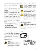
3.23 - BURNER PRESSURE ADJUSTMENT
PK150X 2S
WARNING!
All the instructions indicated below are for the
exclusive use of qualified UNICAL service tech-
nicians or installers.
All the boilers are supplied already calibrated
and tested. However, if it is necessary to change
the calibration, the gas valve must be re-calibra-
ted.
Warning: during this operation do not request any
DHW draw-off .
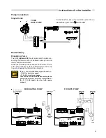
B) Min output adjustment
-
Via the e-bus controller change the "Test" mode and run
the boiler at minimum output (refer to procedure illustra-
ted on page 43).
-
Check that the C02 values are within the values indica-
ted in the table "Burner pressures"
-
If necessary correct the value by turning the adjustment
screw "B" in a CLOCKWISE direction to increase the value
and in an ANTICLOCKWISE direction in order to decrea-
se it.
MAXIMUM OUTPUT ADJU-
STMENT SCREW
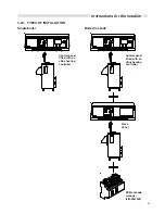
A) Max output adjustment
-
Remove the sampling point cap and insert a suitable C02
gas analyser in the flue outlet terminal.
-
Via the e-bus controller activate the "Test" mode and run
the boiler at maximum output.
-
Check that the C02 values are within the values indica-
ted in the table "Burner pressures"
-
If necessary correct the value by turning the adjustment
screw "A" in a CLOCKWISE direction to decrease the va-
lue and in an ANTICLOCKWISE direction in order to incre-
ase it.
Flue sam-
pling point
Note: To disenable the "Test" mode press the left
key.
C)
COMPLETION OF THE BASIC
ADJUSTMENTS
-
Check the C02 values at the minimum and maximum
input.
-
If necessary make the required adjustments
To ensure correct operation the C02 values
have to be adjusted with extreme care respec-
ting the values indicated in the table.
-
Replace the protective cap on the sampling test point on
the flue outlet terminal.


