


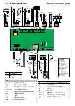


41
Maintenance instructions
ENGLISH
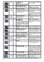
4.6 - ERROR CODES
The symbol flashes on the display monitor when the boiler detects an anomaly.
1) In the event of an anomaly that does not stop boiler operation, press key ‘‘D’’ to
display the error code; in the event the boiler is in stand-by, the error code appears
and remains fixed on the display.
2) In the event of an anomaly that causes boiler down time, the error code flashes
directly on the display.
Each fault is characterised by a priority level: if two faults are detected at the same
time, the code with the highest priority is displayed. The fault codes are listed below:
F) Fault code displayed with code number:
The display flashes alternating the F (FAULT - ANOMALY) with error code (eg 23).
( Num ) =
see key Par. 2.2
SYMBOL
PRIO-
RITY
DESCRIPTION
SOLUTIONS
09
0
EXTERNAL PROBE
interrupted
Check the wiring, if needed
replace the external probe
14
1
RETURN PROBE
Auxiliary
(SRR)
sensor inter-
rupted
Check the wiring, if needed re-
place the auxiliary sensor
(22)
45
2
wATER OVERPRESSURE
detected if the H
2
O pressure
Transducer is present with
pressure > 2.5 bar; it is reset
automatically when H
2
O pres-
sure < 2 bar
Wait for the values to return to
default limits /
Replace the Transducer
30
3
SERVICE PARAMETERS
Service parameters altered due
to possible electromagnetic
interferences.
Reset the altered parameters
via the panel and/or regola
-
facile
21
4
POOR wATER CIRCULATION
Poor circulation in primary
circuit
Check pump operation
(12)
and speed, if there are any
obstructions or system closure.
17
5
FLAME CONTROL FRE-
QUENCY BEYOND LIMIT
Depends on the power supply
mains (Frequency and voltage
beyond default limits)
Wait for the values to return to
the default limits
15
6
wATER CIRCULATION IN-
SUFFICIENT
Primary circuit water circulation
insufficient (∆t > 35° C)
Check pump operation
(12)
and speed - remove any heat
-
ing system obstructions - clean
the scaled domestic hot water
exchanger
22
7
INCORRECT SENSOR PO-
SITIONING
Flow and return
sensors inverted
Check the wiring
(21) (22)
24
8
SPEED OUT OF
CONTROL
Alteration of the fan speed; the
speed is not reached.
Check fan operation
(18)
and
the connections
COD. REGO-
LA FACILE/
FAULT
HISTORY