background image

20

Instruction for the installer

3.12 -   FLUE OUTLET INSTALLATION

The flue system must be installed in accordance with the
local and national Standards (refer to Standard UNI-CIG
7129, point 4 and UNI-CIG point 5)

.

We recommend using only original UNICAL flue
outlet systems.
Damages caused by installation errors and for
non-observance of the instructions given by
the same manufacturer will invalidate all the
supplier’s contractual or extra contractual
responsibilities.

If the boiler has to be replaced ALWAYS replace the flue
outlet system.

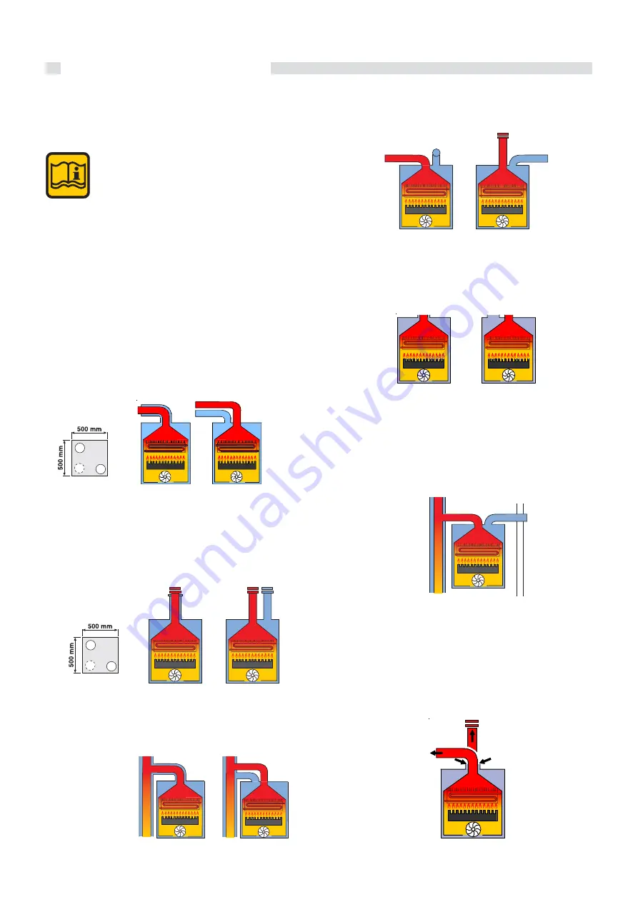
The boiler has been approved for the following flue
configurations:

C13

oiler designed for connection to horizontal inlet and ou-
tlet terminals, which admit fresh air to the burner and
discharge the products of combustion to the outside
through concentric or twin ducts.
The minimum distance between the inlet air duct and
the flue outlet duct must be of 250 mm and both terminals
must be positioned within a 500 mm square section.

C33

Boiler designed for connection to vertical inlet and out-
let terminals, which admit fresh air to the burner and
discharge the products of combustion to the outside
through concentric or twin ducts.
The minimum distance between the air inlet duct and
the flue gas outlet duct must be of 250 mm and moreover
both terminals must be positioned within a 500 mm
square area.

C43

Boiler designed for connection to collective flue systems
including two ducts, one for the air inlet and the other for
the discharge of products of combustion through con-
centric or twin ducts.

C53

Boiler with separate air inlet and products outlet. These
ducts can discharge into areas with different pressure.

The two terminals must not be fitted on to two opposite
walls.

C83

Boiler designed for connection to a terminal for the in-
take of combustion air and to an individual or collective
chimney for the discharge of the products of combu-
stion.

The chimney must comply to the current regulations.

B23

Boiler designed to be connected to an open flue which
will terminate vertically through the roof. The combustion
air is withdrawn directly from the room where the boiler
is installed.

WARNING: for this type of connection the room must
comply with the same installation regulations valid
for open chimney boilers.
The chimney must comply to the current regulations.

aa

aa

aa

aa

aa

aa

aa

aa

aa

aa

aa

aa

aa

aa

aa

aa

aa

aa

aa

aa

Type C63

Boiler designed for connection to a combustion air inlet and
flue products discharge system approved and sold separa-
tely.

Содержание ALKON C 18

Страница 1: ...ALKON 09 R 18 C 18 R 24 C 24 00333176 2nd edition 10 2011 INSTALLATION AND SERVICING MANUAL ...

Страница 2: ...fficiency 29 3 14 Parameters which can be modified from panel board 30 3 15 Electrical connections 31 Connection to mains supply 230V 31 Outdoor sensor connection 32 ON OFF digital room controller connection 33 Layout of the electrical connection for zone control systems 34 3 16 Wiring diagrams 35 Functional flow wiring diagram for Alkon 09 C 35 Functional flow wiring diagram for Alkon 09 R 36 3 1...

Страница 3: ...ear as possible to the one you really require We recommend you to check the state of cleanliness of the domestic hot water heat exchanger at the end of the first year and subsequently on the basis of the lime scale found this period can be extended to two years The user has to be instructed on the use and operation of his heating system in particular Hand over these instructions to the end user to...

Страница 4: ...structive components which influence the appliance s safe operation WARNING When tightening or loosening the screw pipe connections use only adequate fork spanners The improper use and or the use of inadequate equipment can cause damages for example water or gas leakages WARNING Indications for appliances operating with propane gas Ensure yourself that before installing the appliance the gas tank ...

Страница 5: ...EN 13203 1 18 F factor N stars based on the quality of water declared EN 13203 1 19 PMW Max pressure D H W system 20 T max Max temperature D H W system C Electrical features 21 Electrical power supply 22 Consumption 23 Protection grade D Countries of destination 24 Direct and indirect country of destination 25 Gas family 26 Supply pressure E Factory setting 27 Adjusted for gas type X 28 Space for ...

Страница 6: ...cing turn off the electrical supply to the boiler by means of the ON OFF switch and or by means of the appropriate shutdown devices Do not obstruct the inlet outlet terminals In the event of failure and or faulty functioning of the appliance switch off the boiler Do not attempt to make any repairs contact qualified technicians Any repairs must be carried out solely by Unical authorized technicians...

Страница 7: ...sorbed power Minimum heat output adjustment in CH mode Electronic adjustment of the ignition ramp Electronic frost protection mode Pump overrun function Pump overrun function Safety thermostat Flow temperature sensor Return temperature sensor DHW temperature sensor only on the ALKON 09 C mo del Three speed circulating pump with air vent Expansion vessel Automatic air vent Low water pressure switch...

Страница 8: ...N 09 C 1 Condensate drain siphon 2 Domestic hot water temperature sensor 3 Aluminium heat exchanger condenser 4 Flow temperature sensor 5 Overheat safety thermostat 6 Ignition Ionisation electrode 7 Air vent valve 8 Flue outlet combustion air inlet 9 Burner 10 Fan 11 Automatic air vent 12 Return temperature sensor 13 Pump 14 System drain cock 15 Central heating circuit safety valve 16 Filling syst...

Страница 9: ...w water pressure switch 11 Return temperature sensor 12 Expansion vessel 13 Circulation pump 14 Flow temperature sensor 15 By Pass 16 Manometer 17 Central heating circuit safety valve 18 System drain cock 19 Filling system cock 20 Diverter valve M C H system flow C DHW outlet G Gas inlet F Cold water inlet R C H system return 2 4 BOILER WATER CIRCUITS C F G R M 4 1 2 3 5 6 7 8 9 11 13 10 12 14 17 ...

Страница 10: ...Min DHW inlet pressure Max DHW inlet pressure DHW specific flow rate Δt 30 C DHW flow restrictor DHW production in continuous operation with Δt 45 K DHW production in continuous operation with Δt 40 K DHW production in continuous operation with Δt 35 K DHW production in continuous operation with Δt 30 K DHW production in continuous operation with Δt 25 K DHW adjustable temperature Electrical suppl...

Страница 11: ...e gas type available This is verifiable via the indication on the packaging and on the data badge c Check that the chimney flue pipe has an adequate draught does not have any constrictions and that no other appliance s flue outlets have been fitted unless the chimney is serving more than one heating appliance according to the specific standards and regulations in force The connection between the b...

Страница 12: ...ments D M 1 12 1975 Moreover the boiler must be installed in accordance to all the regulations regarding the boiler room and comply to the building regulations and the prescriptions regarding central heating plants in force in the country the boiler is installed The appliance must be installed commissioned and serviced according to the regulations in force This is also valid for the hydraulic syst...

Страница 13: ...itates the connection of the gas and water feed pipes when laying out the hydraulic system and before installing the boiler This template has to be fixed on to the wall chosen for the installation The upper part gives the indications to drill on the wall the fixing holes for the boiler supporting bracket and for the rear smoke outlet The lower part of the template marks the correct positioning of ...

Страница 14: ...ons of diverting valve kit for ALKON 09 R for external D H W tank connection Dimensions for the connection of ALKON 09 R to the external D H W tank DSP 110 DSP110 Hydraulic connection covering kit Pipe connection kit 1970 93 54 56 70 24 51 79 ...

Страница 15: ...tting the boiler Place the steel mounting template on to the wall Determine the position of the holes for fixing the support bracket Drill the holes and fix the support bracket using the fixing screws as indicated on page 13 Engage the boiler on to the support bracket Mark the positions of the gas cold water supply hot water outlet CH flow and return pressure relief valve and or condensate drain N...

Страница 16: ...rmostatic radiator valves lockshield valves and by the system s layout The routing of the piping has to be laid down taking all the necessary precautions in order to avoid air locks and to facilitate the continuous purging of the system Ensure yourself that the system s piping is not used as earth clamps for the electrical or telephonic system They are absolutely unsuitable for this use In a short...

Страница 17: ...s water supply conditions the frequency with which the DHW heat exchanger is cleaned In hard water areas the opportunity of fitting an adequate scale reducing device for domestic purposes for treating the mains water supply to the boiler in compliance to the DM n 443 dated 21 12 90 should be taken into consideration Where water hardness exceeds 15 f a scale reducing device is always recommended En...

Страница 18: ...uced a siphon must be fitted supplied with the boiler there must be no bottlenecks the connection must be made just under the bottom part of the boiler it must be installed so as to avoid freezing of the liquid when the boiler is operating and prevent the eventual pres surization of the sewage system consent the correct downflow of the appliance s liquid di scharges it must be made with one of the...

Страница 19: ...scope of this treatment is finalized for eliminating or substantially reducing the following problems lime scale deposit corrosion sludge deposits microbiological growths moulds bacteria etc An appropriate treatment of the supply water will prevent the above stated problems and will maintain the correct operation and efficiency of the generator in time For this purpose it will be necessary to fix ...

Страница 20: ...entric or twin ducts The minimum distance between the air inlet duct and the flue gas outlet duct must be of 250 mm and moreover both terminals must be positioned within a 500 mm square area C43 Boiler designed for connection to collective flue systems including two ducts one for the air inlet and the other for the discharge of products of combustion through con centric or twin ducts C53 Boiler wi...

Страница 21: ... evacuation duct has to be independent KIT5720C TSC0130C TSC0150C KIT5770C WARNING The combustion air is taken from the room where the boiler is installed If the boiler is installed in an unventilated room convenient ventilation openings need to be done For installations where there is the freezing risk it is suggested to insulate the smoke evacuation duct Ø80 mm in all its length even if its layo...

Страница 22: ...um length permitted has to be reduced by 1 metre Type C13 The minimum allowable length of the horizontal concentric pipes is of 0 75 metres The maximum allowable length of the horizontal concentric pipes is of 3 5 metres For each elbow added the maximum length permitted has to be reduced by 1 metre Important the outlet inlet flue has to have a minimum inclination of 3 towards the top in the outlet...

Страница 23: ...1 metre Moreover the flue outlet has to have a minimum inclination of 3 towards the top in the outlet direction so as to enable the collection of any condensate formed in the boiler Type C33 The maximum allowable length of the vertical concentric pipes is of 8 5 metres including the terminal Ø 80 125 For each elbow added the maximum length permitted has to be reduced by 1 metre HORIZONTAL FLUE OUT...

Страница 24: ...TH SEPARATE DUCTS Ø 80 mm KIT5720C KIT5770C KIT5780C TSC0130C or TSC0150C 120 196 r D 179 r D Ø 80 101 5 237 Fit the rubber spacer supplied with the boiler as shown in the picture It is not permitted to position the two termi nals on opposite walls ...

Страница 25: ...al evacuation duct Ø 80 5 3 m The maximum allowable length of the horizontal separate pi pes Ø 80 is of 58 metres For rectilinear length it is intended without cur ves and suction evacuation terminals For the calculation related to the configurations example 1 or 2 it is necessary to deduct from the maximum allowed length the resistance in meters related to the different accessories see table L ma...

Страница 26: ...take of primary air and flue discharge from two external pe rimeter walls Example N 1 Intake of primary air from the perimeter wall and flue dischar ge from the roof L max 1 Curve with wide radius 1 horizontal suction terminal 1 Vertical evacuation duct With this configuration there are still 47 9 m available to be shared between the suction and evacuation ducts L max 2 curve with wide radius 1 ho...

Страница 27: ...h pipes L max L1 L2 2 Curve with wide radius For each one of them deduct from the maximum allowed Length the corresponding flue losses in meters Table of the flue losses for smoke accessories Ø 60 mm The maximum allowable length of the horizontal separate pi pes Ø 60 is of 20 metres For rectilinear length it is intended without cur ves and suction evacuation terminals or the calculation related to...

Страница 28: ...N 2 Intake of primary air and flue discharge from two external pe rimeter walls L max 1 Curve with wide radius 1 horizontal suction terminal 1 Vertical evacuation duct With this configuration there are still 15 2 m available to be shared between the suction and evacuation ducts L max 2 Curve with wide radius 1 horizontal suction terminal 1 horizontal evacuation terminal With this configuration the...

Страница 29: ...s in force in the destination country 3 13 MEASUREMENT ON SITE OF COM BUSTION EFFICIENCY To determine the combustion efficiency it is necessary to measure The combustion air temperature in the measuring point 2 The smoke temperature and the CO2 value in the measuring point 1 Take the indicated measurements with the boiler in steady state using the special function push button B 2 1 A Analyzer prob...

Страница 30: ... C C To enter the parameters push and keep pressed for ten seconds the reset button release when the flashing wrench appe ars on the display MAX M I N Rotate the HEATING temperature adjustment knob B to select the parameter which needs to be changed Po C nr PH HP the parameters are shown on the display E Confirm the parameter to be changed by pressing the reset button Modify the value of the param...

Страница 31: ...N MAX M I N C C 3 15 ELECTRICAL CONNECTIONS The appliance s electrical safety is guaranteed only when the same appliance has been correctly earthed in compliance with the regulations in force The gas and water feeding pipes and the CH system pipes cannot be used as ground plates Ensure that the above safety electrical requirements subsist in case of doubt ask for a professionally qualified technic...

Страница 32: ...m flow temperature instead HL is automatically set by the boiler when the outdoor temperature is 20 C Once these parameters have been set the boiler will choose a flow temperature on the heating curve on the basis of the outdoor sensor readout Subsequently we have to make the maximum flow temperature correspond to the minimum external temperature by setting the Otc parameter outdoor sensor set poi...

Страница 33: ... terminal strip M1 Remove the link between terminals 1 2 DANGER Switch off and disconnect the electricity supply before carrying out any operations on the electrical parts WARNING The modulating room controllers must be supplied by Unical M1 2 1 M1 2 1 M1 4 3 REGOLAFACILE RT OT 1 2 3 24 18 6 12 PROGRAMMI INTERROMPE ORARIO RISCALDAMENTO PROLUNGA ORARIO RISCALDAMENTO CORREZIONE MANUALE DI TEMPERATUR...

Страница 34: ...manding heat when the diverter valve reaches the low temperature position and sends the request to the boiler The 3 way valve has to use the limit switch contact in order to simulate this type of request When the thermostat s contact On Off is closed the 3 way valve opens the high temperature zone and closes the low temperature zone controlled by the digital room controller Regolafacile With the t...

Страница 35: ... Room Thermostat REGOLAFACILE TA Terminals for ON OFF Room Thermostat FUNCTIONAL FLOW WIRING DIAGRAM ALKON 09 R 18 R 24 YEL GREEN YEL GREEN LIGHT BLUE VG TL DK WHITE BROWN LIGHT BLUE P 230 V 50 Hz E ACC RIL SE OT TA A14 A15 BLACK BLACK WHITE WHITE YELLOW YELLOW BLACK A7 A16 A18 A17 LIGHT BLUE BROWN YEL GREEN N L1 BROWN LIGHT BLUE BROWN MDV RED CH WHITE DHW GREEN VM 5 2 4 1 BROWN PWM BLUE TACHO BLA...

Страница 36: ...UNCTIONAL FLOW WIRING DIAGRAM ALKON 09 C 18 C 24 A7 A18 Connectors DK Safety pressure switch against lack of water E ACC RIL Combined ignition ionisation electrode FL Minimum flow switch MVD Motor of Diverting Valve P Circulating pump SR Heating flow temperature sensor SRR Heating return temperature sensor SS D H W temperature sensor TL Limit thermostat VG Gas valve VM Modulating fan SE Terminals ...

Страница 37: ...ock on the boiler to adjust the pressure This operation must be carried out when the system is cold Use the pressure gauge fitted on the boiler to read the circuit s pressure value NOTE If the boiler has not been fired for a long period the pump could be jammed Before firing the boiler it is important to carry out the following un jamming operation place a cloth underneath the pump remove the pump...

Страница 38: ... up the siphon through the filling hole and check the correct drainage of the condensate If the appliance is used with the condensate drain siphon empty this could cause poisoning caused by the leakage of the flue gasses there are no water leaks all the necessary ventilation conditions and minimum cle arance distances are guaranteed for subsequent servi cing in case the boiler is sited in a cupboa...

Страница 39: ...on mode by rotating the HEATING knob B to its MAX setting and then press the RESET push button for 3 s symbol wrench steady ON and symbol radiator steady ON Check that the C02 values are within the values indicated in the table Burner pressures If necessary correct the value by turning the adjustment screw A in a CLOCKWISE direction to decrease the va lue and in an ANTICLOCKWISE direction in order...

Страница 40: ... 5 6 5 6 50 50 ALKON 09 R 18 C 18 9 5 11 0 5300 5300 20 37 0 47 m h 0 34 kg h 1 90 m h 1 40 kg h Nat gas G20 LPG G31 1800 1800 8 8 x 8 9 5 11 0 5 6 5 6 70 70 INCONVENIENTS SOLUTIONS Noisy flame at cold start Act on the parameter IG via the REGOLAFACILE section TECHNICAL MENU parameters TSP increasing the value by about 5 10 maximum Noisy flame in steady state Increase the CO2 value by 0 2 to 0 4 m...

Страница 41: ...ent maximum input will be of 16 kW Alkon 09 18kW For example with the parameter HP settled on 80 the correspondent maximum input will be of 20 kW Alkon 09 24kW 0 2 4 6 8 01 12 14 16 18 20 22 24 26 28 30 32 34 36 38 40 Maximum imput 0 100 50 7 14 85 70 14 28 21 42 28 56 35 70 42 84 57 14 64 28 71 42 78 56 92 84 0 2 4 6 8 01 12 14 16 18 20 22 24 26 28 30 32 34 36 38 40 Maximum imput 0 100 Output ran...

Страница 42: ... boiler The frequency of servicing will be determined by the service engineer and will depend on the appliance s state of condition These adjustments can be performed only by Service Centres authorized by UNICAL UNICAL is not responsible for any damages caused to persons animals and goods deriving from this infringement For a better operation of your appliance follow the suggested servicing as sho...

Страница 43: ...flue outlet system Check the hydraulic system Combustion analysis Clean the DHW heat exchanger only on the C model Control the efficiency of the electrical and electronic components Check annually Check every 2 years Check efficiency of fan s operation Test for gas soundness Clean the burner and check the ignition efficiency Clean the condensate drain siphon and check that it is discharging correc...

Страница 44: ...y replace the return temperature sensor Working parameters priority 2 Description Working parameters corrupted Possible solutions Re introduce the correct working parameters Insufficient circulation priority 3 Description Insufficient circulation in the primary circuit Possible solutions Inspect the operation of the pump and its speed adjustment Mistension supply to the burner priority 4 Descripti...

Страница 45: ...ntion of the D H W temperature sensor if applicable Possible solutions Check the sensor for good operation see table Resistance Temperature and or its harness C H flow temperature sensor priority 13 Description Intervention of the C H flow temperature sensor Possible solutions Check the sensor for good operation see table Resistance Temperature and or its harness Factory parameters FA priority 14 ...

Страница 46: ......

Страница 47: ......

Страница 48: ...al ag info unical ag com The Unical declines every responsibility for the possible inaccuracies if owed to errors of transcript or press Also reserves the right to bring those changes that it will hold necessary to it own products or profits without jeopardizing its essential characteristics ...

Отзывы: