background image


17 


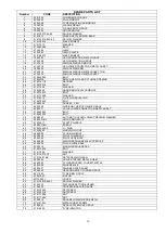
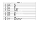
SPARE PARTS LIST 

Number 

CODE 

DESCRIPTION 

73 

01 0013 0650 

– BELT 

74 

72 00 001 

MOTOR PULLEY GROUP 

75 

01 0115 008 

NUT  

76 

01 0062 025 

BOLT 

77 

01 0139 022 

MILE SEGMENT 

78 

01 0082 025 

BOLT 

79 

01 0052 107 

TYRE CHANGER BEAD BREAKER

 RUBBER 

80 

01 0031 37 

ARM PULLING SPRING 

81 

01 0117 016 

NUT  

82 

11 00 006 

BEAD BREAKER PULLING METAL 

83 

11 00 005 

BEAD BREAKER CONNECT PIN 

84 

47 30 000 

BEAD BREAKER GROUP 

85 

01 0014 91-M 

QUICK CAPLIN RECORD MALE 

86 

01 0014 54 

RECORD 

87 

01 0198 13.5 

PLASTIC CABLE RECORD 

88 

01 0014 99-PL 

RECORD 

89 

01 0014 207 

RECORD 

90 

11 00 020 

NUT 

91 

11 00 019 

REDUCTION 

92 

01 0014 80 

SLEEVE 

93 

01 0014 15 

RECORD 

94 

43 00 011 

BEAD BREAKER CYLINDER CONNECT BOLT 

95 

01 0550 01 

BEAD BREAKER CYLINDER GROUP 

96 

01 0063 030 

BOLT 

97 

01 0139 014 

MILE SEGMENT 

98 

48 01 010 

PISTON CONNECTION MILE 

99 

01 0139 018 

MILE SEGMENT  

100 

01 0139 012 

MILE SEGMENT 

101 

01 0139 040 

MILE SEGMENT  

102 

01 0031 136 

BACK STRECHING METAL PUSHING SPRING 

103 

91 00 013 

STRECHING METAL GAUGE PIN 

104 

01 0014 269 

NIPPEL 

105 

91 00 002 

STRECH MOVEMENT METAL SHEET 

106 

91 00 011 

HOSE WAY PIPE  

107 

01 0031 32 

BACK STRECH SPRING 

108 

01 0124 040 

SETSCREW 

109 

01 0014 01 

RECORD 

110 

01 0014 138 

RECORD 

111 

01 0063 040 

BOLT 

112 

01 0117 010 

NUT 

113 

01 0130 040-50-1 

RAYNEL WASHER  

114 

01 0117 018-1.5 

NUT  

115 

01 0115 018 

NUT 

116 

01 0112 18 

WASHER 

117 

80 00 012 

PILLAR SLIDING MILE 

118 

91 00 007 

TYRE MOUNTING ARM STRECTHING METAL 

119 

59 09 000 

BACK STRECHING CYLINDER GROUP 

120 

11 16 000 

STRECHING  CYLINDER GROUP 

121 

91 00 005 

SLIDING REEL MILE 

122 

91 00 004 

SQUARE SLIDING REEL  

123 

91 00 006 

FRONT STRECHING MILE 

124 

11 00 003 

MOTOR CONNECT METAL SHEET 

125 

01 0063 170 

BOLT 

126 

01 0112 10 

WASHER 

127 

01 0063 200 

BOLT 

128 

01 0086 080 

BOLT 

129 

01 0029 14 (DAMING) 

BRAVA REDUCTION 

130 

01 0073 016 

BOLT 

131 

91 00 012 

HEAD REMOVAL CYLINDER LOWER CONNECTION MILE 

132 

91 00 020 

UPPER BIG ABS 

133 

91 00 018 

PILLAR UPPER ABS 

134 

11TI 23 000 

AIR DISTRIBUTOR GROUP 

135 

91 05 000 

PEDAL GROUP 

136 

01 0550 06 

HEAD REMOVAL CYLINDER  

137 

91 05 001 

PEDAL BODY GROUP 

138 

91 05 002 

HEAD BREAKING AND FLANGE PEDAL GROUP 

139 

91 05 003 

BEAD BREAKER PEDAL GROUP 

140 

91 05 004 

POWER SWITCH PEDAL GROUP 

141 

91 05 007 

PEDAL CONNECTION MILE 

142 

91 05 010 

PEDAL INTERMEDIATE METAL  BIG  

143 

91 05 011 

PEDAL INTERMEDIATE METAL  SMALL 

144 

91 05 018 

BEAD BREAKER VALVE GROUP 

145 

91 05 017 

FLANGE CYLINDER VALVE GROUP  

146 

91 05 016 

HEAD REMOVAL CYLINDER VALVE GROUP 

147 

01 0072 025 

BOLT 


Содержание MANAGER

Страница 1: ...1 MANAGER THE MANUAL ENGLISH AUTOMATIC TYRE CHANGER ...

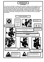
Страница 2: ...nd production defects the damaged parts will be replaced with new ones The warranty covers all parts of the machine NOTE for the electric motor to be under warranty a thermal switch matching the motor current must be placed in the electric wiring otherwise in case of any fault the electric motor will not be covered by the warranty Perform maintenance on the machine periodically monthly once a year...

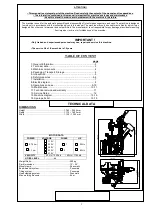
Страница 3: ...achine may only be used for activities for which it was designed Any other use is improper and not permitted The manufacturer is not responsible for any damage or accidents resulting from improper incorrect or forbidden use of the machine IMPORTANT Only trained and experienced personnel may use repair and service this machine The service life of the machine is 10 years TABLE OF CONTENT page 1 Gene...

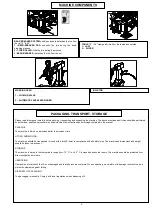
Страница 4: ...and all the instructions and warnings contained in the manual PACKAGE The machine is stored on a wooden pallet in a wooden crate LIFTING AND MOVING The machine should be transported moved with a forklift hoist in compliance with all safety rules The machines s dimensions and weight should be taken into account STORAGE The machine is stored in the temperature range from 10 C to 40 C in closed and s...

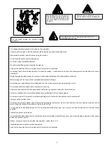
Страница 5: ...hout gloves and glasses Keep hands away from the machine shaft Do not open the cover of the machine under voltage It could cause an accident If necessary contact the manufacturer s service department WARNING BEFORE OPENING THE COVERS DISCONNECT THE POWER SUPPLY Do not get your hands or feet between the bead breaker and the tyre Do not put your hands between the jaws on the table Do not put your ha...

Страница 6: ...chanical and chemical damage Don t let it get damaged Do not use the cable if it is partially or completely damaged torn contact our technical service for replacement Always keep the machine clean Do not use the pressure washer when cleaning and maintaining the machine Do not use conductive or semi conductive materials such as water Protect the machine from moisture rain snow hail or fog The machi...

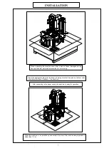
Страница 7: ... the appropriate plug into the device the plug must be three phase the four cells should contain these 3 phases 1 neutral wire After connecting to the power supply the machine is ready for operation When the machine is in operation no one except the user of the machine may approach it closer than 1 5 m INSTALLATION 1 5m 1 5m 1 5m 1 5m ...

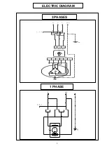
Страница 8: ...8 ELECTRIC DIAGRAM 1 PHASE 3 PHASES 2 1 1 13 6 3 11 8 2 L3 14 2 5 1 L1 0 L2 PE 1 0 2 T R S MP ...

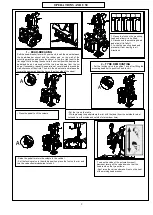
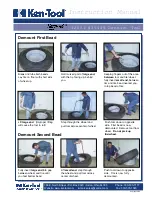
Страница 9: ...r lifting the mounting head set to position 3 and lock it Press the pedal to tilt the column Put the tyre on the table While pressing the pedal clamp the rim with the jaws from the outside for steel rims and from the inside and outside for aluminum rims Raise the pedal to return the column to the vertical Set the locking valve to the middle position place the foot on the rim and turn the valve cou...

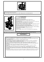
Страница 10: ...sories Before carrying out any adjustments or maintenance to the machine disconnect the power supply and check that all moving parts are properly secured Do not disassemble or modify any part of the device This does not apply to servicing Check that the jaws move freely daily Contamination accumulated during the operation of the machine may significantly deteriorate the sliding of the jaws thus cr...

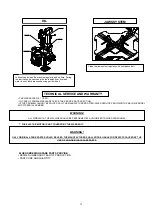
Страница 11: ...DUCTION PART CODE AND QUANTITY TECHNICAL SERVICE AND WARRANTY OIL Lubricate and clean the machine regularly and on time During the lubrication process keep the tools away from dust and water do not lubricate unnecessary parts with oil JAWS SYSTEM Clean the jaw system regularly with compressed air WARNING ALL WORK WITH THE MACHINE SHOULD BE PERFORMED BY AUTHORIZED TRAINED PERSONNEL WARNING ONLY ORI...

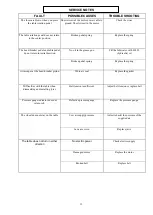
Страница 12: ...lic oil Broken pedal spring Replace the spring Air escapes at the bead breaker piston Worn air seal Replace the gasket Difficulties with the table when dismantling and installing tyres Belt tension insufficient Adjust belt tension or replace belt Pressure gauge indicator does not return to 0 Defective pressure gauge Replace the pressure gauge The wheel does not stay on the table Low air supply pre...

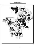
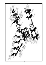
Страница 13: ...0 11 003A 01 0072 010 01 0014 55 PC 93TÝ 00 001 01 0107 033 01 0014 56 PC 01 0014 55 PC 01 0105 016 11TÝ 23 001 01 0123 025 93 00 009 43 00 011 01 0063 200 01 0112 10 01 0550 01 01 0117 010 01 0029 14 DAMING 01 0014 157 93 01 000 11 22 001 01 0024 065 3 01 0062 025 11 00 003 01 0013 0650 91 00 020 72 00 001 01 0278 63 01 0550 06 48 01 010 01 0139 014 01 0139 018 01 0117 006 11TÝ 20 003 01 0014 12 ...

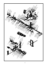
Страница 14: ... 1 0 1 2 4 0 4 0 0 1 0 3 6 0 0 6 0 0 4 5 1 0 1 1 1 6 0 0 1 0 1 0 0 1 4 1 3 8 0 1 0 1 1 7 0 1 0 0 1 0 1 1 2 1 0 1 1 1 6 0 0 2 8 0 0 8 0 0 2 8 0 0 8 0 0 3 5 9 0 6 0 0 3 0 1 0 1 1 2 0 8 0 1 0 1 1 7 0 0 8 0 1 0 1 3 9 0 4 0 0 1 0 1 3 0 0 4 0 5 0 1 0 1 0 0 1 4 6 2 N S E 0 1 0 0 7 3 0 2 5 0 1 0 1 1 2 0 8 9 3 0 0 0 0 2 9 3 0 0 0 0 8 0 1 0 1 1 7 0 0 8 0 1 0 1 1 2 0 8 0 1 0 0 4 8 1 7 9 3 0 0 0 0 1 M L 0 1 0...

Страница 15: ...1 0 0 1 0 1 1 7 0 0 6 0 1 0 0 7 2 0 1 6 9 1 0 5 0 0 9 0 0 0 1 0 0 0 1 9 1 0 5 0 2 0 0 1 0 0 8 1 0 1 6 0 1 0 0 7 2 0 3 5 9 1 0 5 0 1 3 9 1 0 5 0 0 6 9 1 0 5 0 1 2 9 1 0 5 0 1 9 0 1 0 0 8 1 0 1 6 0 1 0 1 3 0 0 1 2 0 1 8 0 5 9 1 0 5 0 1 4 9 1 0 5 0 0 5 9 1 0 5 0 2 5 0 1 0 0 3 1 1 3 5 0 1 0 2 0 0 3 2 5 9 0 7 0 1 3 0 1 0 0 7 3 0 5 5 0 1 0 1 3 9 0 0 6 9 1 0 5 0 2 6 0 1 0 0 7 2 0 2 0 0 1 0 1 3 9 0 1 2 9 ...

Страница 16: ...052 56 PROFILE LEG 34 48 09 000 SIDE BODY HEIGHT GAUGE GROUP 35 93 00 011 VALVE LOWER CONNECTION MEATL SHEET 36 01 0063 025 BOLT 37 01 0083 035 BOLT 38 80 00 007 AUTOMATIC LEVER LOWER PRESSING WASHER 39 93 00 001 ML HOLD ARM GROUP 40 01 0048 17 PLASTIC HANDLE 41 80 00 017 ML BURSH 42 01 0024 042 6 O RING 43 01 0550 03 MOUNTING FOOT 44 48 00 000 PLUS MAIN BODY 45 93 00 004 RIGHT LOWER CAP 46 93 00 ...

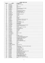
Страница 17: ...1 0124 040 SETSCREW 109 01 0014 01 RECORD 110 01 0014 138 RECORD 111 01 0063 040 BOLT 112 01 0117 010 NUT 113 01 0130 040 50 1 RAYNEL WASHER 114 01 0117 018 1 5 NUT 115 01 0115 018 NUT 116 01 0112 18 WASHER 117 80 00 012 PILLAR SLIDING MILE 118 91 00 007 TYRE MOUNTING ARM STRECTHING METAL 119 59 09 000 BACK STRECHING CYLINDER GROUP 120 11 16 000 STRECHING CYLINDER GROUP 121 91 00 005 SLIDING REEL ...

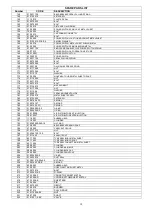
Страница 18: ...6 WASHER 180 01 0550 13 PEDAL MOVEMENT GUIDE 181 01 0105 016 METAL SHEET SCREW 182 01 0123 025 SETSCREW 183 01 0014 56 PC RECORD 184 01 0014 157 RECORD 185 01 0014 55 PC RECORD 186 01 0024 090 2 5 O RING 187 01 0024 065 3 O RING 188 00 01 0028 AIR DISTRIBUTOR EXIT INJECTION 189 00 01 0027 AIR DISTRIBUTOR ENTER INJECTION 190 11 16 001 RUBBER HEAD 191 11 16 002 CYLINDER 192 01 0360 060 045 10 NUT RI...

Страница 19: ...DLE 233 01 0122 010 SETSCREW 234 11Tİ 20 007 SHEET METAL 235 11Tİ 20 000 FLANGE CYLINDER VALVE GROUP 236 11Tİ 20 003 SHOCK SHAFT 237 01 0031 06 SPRING 238 93Tİ 00 002 TREADLE PROJECT SHEET METAL 239 01 0014 13 RECORD 240 01 0014 12 RECORD 241 01 0014 61 PST RECORD 242 01 0031 34 SPRING 243 01 0141 04 024 PIN 244 11 12 007 SHEET BAR 245 11 12 008 BUSHER 246 11 22 001 DISTRIBUTOR INLET GROUP 247 11T...

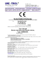
Страница 20: ...romagnetic compatibility directive 2014 68 EU pressure In order to verification of compliance with the applicable legal regulations have been consulted harmonized standards and other normative documents PN EN ISO 12100 2012P Safety of machinery General principles for design Risk assessment and risk reduction PN EN 61000 6 3 2008P Electromagnetic compatibility EMC Part 6 3 General standards Emissio...

Страница 21: ...EE The technical documentation of this device referred to in point 1 of Annex VII A of the Machinery Directive is located in the headquarters of manufacturer and will be made available to the competent national authorities for at least 10 years after the last piece The person responsible for the preparation of the technical documentation of the product and introducing changes in it is MSc Gregory ...

Отзывы: