background image


EYE XO2


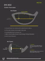
Club Sticker Placement


EYE XO2  INSTALLATION  GUIDE                    

    24


Содержание EYE XO2

Страница 1: ...INSTALLATION GUIDE EYE XO2 IMPORTANT Read Before Using...

Страница 2: ...l current to reduce the risk of electric shock This tool is equipped with an electrical cord having an equipment grounding conductor and a grounding plug The plug must be plugged into a matching outle...

Страница 3: ...ING To Ensure Safe Use 4 5 1 Installation Environment 6 2 Included Items 7 3 Hardware Install 8 3 1 Mounting Bracket 9 3 2 Slide Sensor 10 3 3 Connection 3 4 Connection Status 11 12 5 Software Install...

Страница 4: ...NING Used for instructions intended to alert the user to the risk of severe injury should the unit be used improperly Used for instructions intended to alert the user to the risk of injury or material...

Страница 5: ...r in any location where exposure to water or high humidity may occur Do not touch the power cord or electrical outlet with wet or dirty hands Doing so may result in electrical shock Conduct play in a...

Страница 6: ...ntel i5 8400 or higher RAM 8 GB Graphics Card GeForceGTX 1060 or higher Operating System Windows 10 64bit Version 1803 or higher Resolution 1920 x 1080 Connectivity Ethernet Port Required AMD 3rd gen...

Страница 7: ...sure they are all present and accounted for EYEXO2 Sensor Bar Bracket Email Software Installer Calibration Chart Power Cable Power Adapter Power Connector USB EthernetAdapter Ethernet LAN Cable Level...

Страница 8: ...9 M4 32mm screws are required to screw in the bracket and hold the sensor Failure to do so may result in serious injury or damage to property CAUTION Two or more persons are recommended for mounting t...

Страница 9: ...feet from the front and middle of the sensor to your tee position Do NOT align to the bracket Place the ladder under the location on the ceiling where the bracket will be mounted Place the bracket fl...

Страница 10: ...o the bar and even in length Slide the sensor bar with the 6 screws up and over through the bracket hinges Make sure the screws are secured in the hook part of the hinges Once the sensor is secured in...

Страница 11: ...Y to your PC ethernet port and NOT the USB adapter Take out all 3 components of the power source power cable power adapter and power connector Connect all 3 accordingly and connect the Power Connector...

Страница 12: ...status before you start the software installation process Check and see if the power is on You will see a bright red light on the switch of the sensor Check and see if your EYE XO2 Sensor and PC are p...

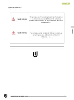
Страница 13: ...are met from section 1 Installation Environment before the installation process Failure to do will result in installation issues and slow gameplay WARNING Please make sure the connection statuses are...

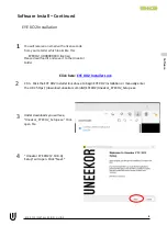
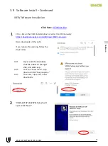
Страница 14: ...ve it to the Uneekor Folder Click here EYE XO2 Installer Link Ctrl Click the EYE XO2 Installer link above to begin EYE XO2 Installation or manually enter the URL https download uneekor com dist EYEXO2...

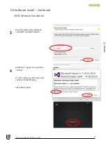
Страница 15: ...INSTALLATION GUIDE 15 3 5 Software Install Continued EYE XO2 Software Installation Keep the destination folder as C Uneekor and click Install Please wait while installer completes installation 5 6 So...

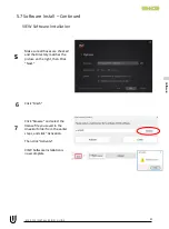
Страница 16: ...INSTALLATION GUIDE 16 3 6 Software Install Continued EYE XO2 Software Installation If these two pop ups occur please hit ok for both The Run Uneekor EYE XO2 is checked Uncheck it and click finish 7 S...

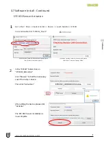
Страница 17: ...on EYEXO2_Activation Click Browse to find the license key saved from step 1 above Then click Activation After adding the license please click Activate The EYE XO2 Sensor installation is now complete 2...

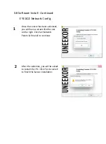
Страница 18: ...nfig 1 Once the sensor has been activated you will have a screen like the one on the right Click Set Network Param Firewall to continue 2 After the selection you will be asked to restart the PC Click...

Страница 19: ...3 8 Software installation Continued EYE XO2 Calibration To complete the installation of the EYE XO2 Follow the calibration guide linked below EYE XO2 Calibration Guide EYE XO2 INSTALLATION GUIDE 19...

Страница 20: ...d uneekor com dist View VIEW_Setup exe Open downloads on the right If you receive this warning follow the steps below 3 8 1 Hover over the download click the 3 dots on the right side and click keep 3...

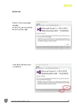
Страница 21: ...ftware Install Continued VIEW Software Installation Keep the Destination Folder as C VIEW and click Install Check the I agree box and click Install If a error pops up click close and continue to VIEW...

Страница 22: ...If the C files are already installed on your PC you may receive the error on the right Click Close and then next to continue Optional EYE XO2 INSTALLATION GUIDE 22...

Страница 23: ...all boxes are checked and the Directory matches the picture on the right then Click Next Click Finish Click browse and select the license file you saved in the Uneekor folder from the earlier steps an...

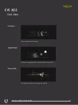
Страница 24: ...lub Data Club Speed The speed of the club before impact The amount of energy transferred from the club head to the golf ball The angle difference between Face Angle and Club Path EYE XO2 INSTALLATION...

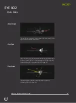
Страница 25: ...o out or out to in movement of the club head s geometric center at the time of impact Club Path is the directon right or left the club head is moving at impact and is measured relative to the target l...

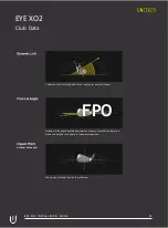
Страница 26: ...t the center point of impact Lie angle is the angle created between the center of the shaft and ground when you put your iron down in the address position Vertical Horizontal Where you strike the ball...

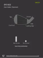
Страница 27: ...EYE XO2 Club Sticker Placement EYE XO2 INSTALLATION GUIDE 24...

Страница 28: ...ould line up to the middle of the Bar sticker 3 Avoid placing both stickers near the sweet spot 5 Attach in line with the grooves Iron 13 groove 1 Bar Sticker Align the middle of the Bar Sticker to th...

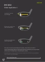
Страница 29: ...ed inside the club face for proper reading All 4 corners of the stickers must be attached to the club face If the club face is short and all 4 horiztonal line so all of the Bar Sticker can be placed i...

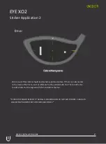
Страница 30: ...er on the crown of the driver use it as reference for the vertical center line The top of the bar and dot sticker must be aligned with the horizontal center line CLUB DATA CANNOT BE READ IF THE BALL I...

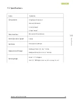
Страница 31: ...Boards 1 Control Board 1 Power Board Data Interface Ethernet CAT6 and above Communication Speed 1 Gbps Spin Data Total Spin 12 000 rpm Measurement Range Ball Speed Putter 0 1 m s 30 m s Ball Speed Dr...

Страница 32: ...MASTER YOUR PASSION Uneekor Inc 15770 Laguna Canyon Rd Suite 100 Irvine CA 92618 sales uneekor com support uneekor com Uneekor 2023 All Rights Reserved...

Отзывы: