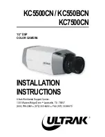
Ultrak KC5500CN Скачать руководство пользователя страница 15

7

2.2 KC7500CN

Continued on next page

6

6

TOP VIEW

ON    OFF

BOTTOM VIEW

FRONT VIEW

BACK VIEW

1             2   3 4    5         6                      7                      8     

9                  10                                  11

12

VIDEO OUT

CLASS 2

G

PWR

12VDC/24VAC

PLL

SHUTTER

A

E

F

G

H

I

B

C

LO

C

K

LE

N

S

C

CS

18

SHT

R

E/I

GAM

AGC

A/I

N.C

AWB1

AWB2

BLC

1

BLC

2

IRIS

on

of

f  

of

f  

off 

 v

id


of

f  

of

f  

of

f  

of

f

of

f  

on


o

n  

on


dc


on


o

n  

on


on

Содержание KC5500CN

Страница 1: ...KC5500CN KC550BCN KC7500CN 1 3 DSP COLOR CAMERA INSTALLATION INSTRUCTIONS Ultrak Worldwide Support Center 1301 Waters Ridge Drive Lewisville TX 75057 800 796 2288 972 353 6400 FAX 972 353 6670...

Страница 2: ...N MAY BE REPRODUCED BY ANY MEANS WITHOUT WRITTEN PERMISSION FROM ULTRAK THE INFORMATION IN THIS PUBLICATION IS BELIEVED TO BE ACCURATE IN ALL RESPECTS HOWEVER ULTRAK CANNOT ASSUME RESPONSIBILITY FOR A...

Страница 3: ...D STATUTES The lightning flash with arrowhead symbol within an equilateral triangle is intended to alert the user to the presence of uninsulated dangerous voltage within the product s enclosure that m...

Страница 4: ...his is a safety feature If you are unable to insert the plug fully into the outlet try reversing the plug If the plug should still fail to fit contact your electrician to replace your obsolete outlet...

Страница 5: ...CE TO RADIO OR TELEVISION RECEPTION WHICH CAN BE DETERMINED BY TURNING THE EQUIPMENT OFF AND ON THE USER IS ENCOURAGED TO TRY TO CORRECT THE INTERFERENCE BY ONE OR MORE OF THE FOLLOWING MEASURES REORI...

Страница 6: ...vi THIS PAGE INTENTIONALLY LEFT BLANK...

Страница 7: ...7 2 2 1 KC7500CN Camera Back 8 2 2 2 KC7500CN Camera Front 9 2 2 3 KC7500CN Camera Top 9 2 2 4 KC7500CN Camera Bottom 11 SECTION 3 CAMERA INSTALLATION AND ADJUSTMENT 13 3 1 CONTENTS OF PACKAGE 13 3 2...

Страница 8: ...viii THIS PAGE INTENTIONALLY LEFT BLANK...

Страница 9: ...of resolution KC7500CN 1 lux F1 4 sensitivity C CS backfocus cam for easy adjustment Auto electronic shutter and manual electronic shutter modes from 1 60 to 1 100 000 Auto and manual white balance mo...

Страница 10: ...2 THIS PAGE INTENTIONALLY LEFT BLANK...

Страница 11: ...inued on next page LOCK LENS C CS 1 8 A D E F G H I C E I GAM AGC A I BLC AWB1 AWB2 IRIS on off off off vid off off off off on on on dc on on on TOP VIEW BOTTOM VIEW VIDEO OUT CLASS 2 G PWR 12VDC 24VA...

Страница 12: ...vertical flip or roll on the monitor while using an auto switcher 2 Power Input Terminal This terminal accepts a 24V ac power source from a 24V ac 10 60Hz 1 or 12V dc 10 using a UL listed Class 2 pow...

Страница 13: ...it is positioned toward the front of the camera If the position is set toward the back of the camera the switch is OFF The switches include Iris Adjustment Pot Potentiometer This control allows the us...

Страница 14: ...on switch allows 45 correction for non linearity gain response in the monitor when set to ON When set to OFF there is no gamma correction E I When set to the ON position the electronic iris switch aut...

Страница 15: ...BOTTOM VIEW FRONT VIEW BACK VIEW 1 2 3 4 5 6 7 8 9 10 11 12 VIDEO OUT CLASS 2 G PWR 12VDC 24VAC PLL SHUTTER A E F G H I B C LOCK LENS C CS 1 8 SHTR E I GAM AGC A I N C AWB1 AWB2 BLC1 BLC2 IRIS on off...

Страница 16: ...is no vertical flip or roll on the monitor while using an auto switcher 2 Power Input Terminal This terminal accepts a 24V ac power source from a 24V ac 10 60Hz 1 or 12V dc 10 using a UL listed Class...

Страница 17: ...ches This compartment houses switches for camera operation A switch is in the ON position if it is positioned toward the front of the camera If the position is set toward the back of the camera the sw...

Страница 18: ...switch is useful when using the camera at low light levels and when lighting levels change over time GAM Switch The gamma correction switch allows 45 correction for non linearity gain response in the...

Страница 19: ...11 2 2 4 KC7500CN Camera Bottom 12 Mounting Bracket Hole This threaded 20 hole is used to mount the camera onto a mounting bracket or tripod...

Страница 20: ...12 THIS PAGE INTENTIONALLY LEFT BLANK...

Страница 21: ...t The contents of the package includes 1 Color CCD camera 2 Mini DIN connector for video or dc type auto iris lens 3 2 BASIC INSTALLATION After unpacking and identifying the package contents perform t...

Страница 22: ...object such as a wall stud or ceiling rafter that can support the weight of the camera and mount IMPORTANT The minimum recommended load rating for the mounting bracket is 11 lbs 5Kg 4 The observation...

Страница 23: ...Care should be taken when routing the cable from the monitor to the camera Try not to put unnecessary strain on the cable or connectors Do not place the cable next to fluorescent lights as interferen...

Страница 24: ...the negative pole to the negative position Use only a Class 2 power source 11 Apply 24V ac or 12V dc power to the camera 12 Plug the monitor s power cable into a suitable wall outlet 13 Turn on the mo...

Страница 25: ...era s depth of field slightly close the manual iris by approximately five to ten percent 3 4 VIDEO TYPE AUTO IRIS LENS INSTALLATION AND ADJUSTMENT The cameras support video type auto iris lenses to ad...

Страница 26: ...e that the E I switch located on the back of the camera is set to OFF and the A I switch is set to Video 5 Apply power to the camera 6 Adjust the focus ring on the lens for an optimum picture If the p...

Страница 27: ...s setting if you want to see the brightest object and not the background objects For Level adjustments Adjust the Level control for the best picture during the day A night adjustment may not provide t...

Страница 28: ...he connector that comes supplied with the camera to the lens control wires The pin out and wire color coding for DC type auto iris lenses can vary from one manufacturer to another 3 Plug the connector...

Страница 29: ...focus adjustments perform the following 1 After mounting the lens on the camera apply power 2 If a picture is visible focus on the scene If a picture is not visible open the iris on the lens Open the...

Страница 30: ...is of the lens is wide open For best results make the adjustment by using a 6 or 8 welder s glass placed in front of the lens 3 Adjust the focus on the lens to the far range 4 Adjust the zoom on the l...

Страница 31: ...that the camera remains in focus after tightening the lock screw On occasion tightening the lock screw can cause the camera to be slightly out of focus 12 Repeat the previous steps as many times as ne...

Страница 32: ...24 THIS PAGE INTENTIONALLY LEFT BLANK...

Страница 33: ...e the system is plugged in Make sure the main power switch on the back of the observation monitor is in the ON position Check the outlet for power POWER BUT NO PICTURE Verify power to all pieces of eq...

Страница 34: ...26 THIS PAGE INTENTIONALLY LEFT BLANK...

Страница 35: ...etection and correction of minor faults before they become serious and cause equipment failure Every three months perform the following A Inspect all connecting cables for deterioration or other damag...

Страница 36: ...mination 1 0 Lux F1 4 Video Output 1 0 Vp p 75 Ohms unbalanced Sync System Line lock Electronic Shutter 1 60 1 100 000 sec Lens Mount C or CS mount adjustable backfocus ring Camera Mount 20 UNC top bo...

Отзывы: