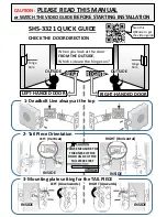
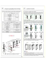
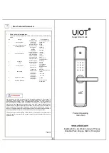
Product List and Installation Explosion Diagram
III
Please check carefully according to the following list after unpacking the packing
case. If any omission is found, please contact our company or local agent in time.
Product List
No.
Name
Number of locks per
set
Remarks
1
Outer cover plate
1
2
Inner cover plate
1
3
Inner bottom plate
1
4
Inner rubber pad
1
5
Lock body
1
6
Screw kit
1
See the table below
for details.
7
Board buckle plate
and case
1
8
Anti-theft door
buckle plate
1
9
Card (optional)
2
List of screw packages (40~90 door thick)
No.
Name
Quantity
Remarks
1
Cross countersunk self-tapping
screw
6
ST4.2X20 for wooden door installation
2
Cross countersunk screw
8
M5X10 for iron gate installation
3
Cross pan head screw
4
M5X15 inner cover plate is fixed to the
inner bottom plate
4
Cross pan external tooth two
combined screw
3
M5X35 is suitable for 50~70mm door
thickness
5
Cross pan external tooth two
combined screw
3
M5X65 is suitable for 75~90mm door
thickness
6
Cross pan external tooth two
combined screw
3
M5X25 is suitable for 40~50mm door
thickness
7
Square bar
1
8
Counter-lock bar
1
9
Allen wrench
1
For fixing external handle
10
Square bar guide seat (plastic)
1
For inner bottom plate mounting guide
(must be used)
11
Cover plate screw hole
2
12
Locating pin
1
For fixing the counter-lock square bar
13
Connecting pipe
3
For fixing inner and outer plates
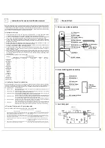
Installation Explosion
Diagram
Outer cover
plate
Square bar
Inner rubber pad
Inner bottom plate
Inner cover plate
Cover plate screw
Battery compartment
cover
Connecting pipe
Lock body
Tapping screw
Bottom plate screw
Note:
This part is only used for installing the locating square bar, and
it shall be removed when installing the inner cover plate
IV
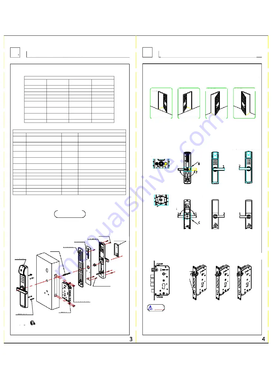
Installation Instructions
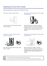
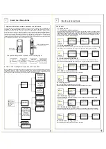
1. Door direction confirmation before installation
The smart door lock is suitable for four kinds of doors with left outer opening, left inner
opening, right outer opening and right inner opening. Determine the direction of the
handle according to the left or right opening, and determine the direction of the oblique
bolt according to the inner or outer opening. As shown in the following figure
2.Handle direction change
Use an Allen wrench and a Phillips screwdriver to unscrew the Allen screw and the
handle fixing screw, pull out the handle moderately, rotate 180° to the correct position,
and then screw back the screw. Rotate along the right outer opening and right inner
opening handle directions to position 1, and along the left inner opening and left outer
opening handle directions to position 2. The specific steps are shown in the following
figure
Right inner opening
Left inner opening
Right outer opening
Left outer opening
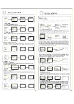
Outer cover plate
B: After unscrewing the two
screws with a screwdriver,
turn the handle 180° to the
key hole surface to the
correct position and then
screw back the screws.
Internal handle
direction change
Direction of external
handle for right opening
Direction of external
handle for left opening
C: Turn on the safety
button, unscrew the two
screws with a screwdriver,
rotate the handle 180° to
the correct position and
then screw back the
screws.
Inner cover plate
Direction of internal
handle for left opening
Direction of internal
handle for right opening
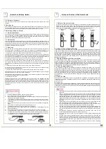
3. Lock body oblique bolt direction change
The direction of oblique bolt for right outer opening and left inner opening is as shown
in fig. 1; The direction of oblique bolt for right inner opening and left outer opening is as
shown in fig. 2. The specific steps are shown in the following figure
Lock body
Lock body Direction
change
Figure 1
Figure 2
Use a Phillips
screwdriver to
unscrew the
lock body panel
screw. After the
panel is
removed, rotate
the oblique
tongue180°,
then install the
panel into the
lock body, and
lock screw
Caution
1.
Before installation, be sure to determine the direction of door opening and switch the handle and
oblique bolt according to the installation instructions.
2.
After the whole lock is installed, open the sliding cover of the front cover plate, enter any 6-12 digit
password, or enter any line to imitate the unlocking action. If the front handle is pressed down when
the LED indicator light is on and the green light is on, the installation is completed if the lock body
oblique bolt and the main bolt can be normally controlled.
Remember that no one is allowed to close
the door outside the door until the installation is confirmed to be completed
External handle
direction change