


C50/C75-MAN
P. 6
Combustion Efficiency Calculation
The efficiency calculation is based upon British Standards BS845.
This identifies three sources of loss associated with fuel burning:
Losses due to flue gasses:
Dry Flue gas loss, moisture and
hydrogen, sensible heat of water
vapor, unburned gas
Losses due to refuse:
Combustible in ash, riddlings
and dust
Other losses:
Radiation, convection, conduction
other unmeasured losses
Net efficiency calculations assume that the energy contained in the
water vapor (formed as a product of combustion and from wet fuel) is
recovered and the wet loss term is zero. Gross efficiency calculations
assume that the energy contained in the water vapor is not recovered.
Since the fuel air mixture is never consistent there is the possibility of
unburned/partially unburned fuel passing through the flue. This is
represented by the unburned carbon loss.
Losses due to combustible matter in ashes, riddlings, dust and grit,
radiation, convection and conduction are not included.
Efficiency Calculation:
Known Data - Fuel: Qgr = Gross Calorific Value (kJ/kg)
Qnet = Net Calorific Value (kJ/kg)
K1 = Constant based on Gross or net Calorific Va l u e
K1g = (255 x % Carbon in fuel)/Qgr
K1n = (255 x % Carbon in fuel)/Qnet
K2 = % max theoretical CO
2
( d ry basis)
K3 = % Wet loss
H
2
= % Hydrogen
H
2
O = % Wa t e r
Measured Data:
Tf = Flue Temperature
Ti = Inlet Temperature
O
2
m = % Oxygen in flue gas
O
2
r = Oxygen reference %
Calculated Data:
Tnet = Net Temperature
% CO
2
content in flue gas
% Dry flue gas losses
% Wet losses
% Unburned carbon loss
% Efficiency
Tnet
= Flue Temperature - Inlet Temperature
(or ambient)
D ry flue gas loss % = 20.9 x K1 x (Tnet)/K2 x (20.9 - O
2
m)
Wet loss %
= 9 x H
2
+ H
2
O/Qgr x [2488 + 2.1 Tf - 4.2 Ti]
S i m p l i f i e d
= [(9 x H
2
+ H
2
O)/Qgr] x 2425 x [1 + 0.001 Tnet]
Wet loss %
= K3 (1 + 0.001 x Tnet)
Where K3
= [(9 x H
2
+ H
2
O)/Qgr] x 2425
C o m b u s t i o n
Combustion Theory
In its simplest form, combustion is the combining of oxygen (O
2
) from
the air with hydrogen (H) and carbon (C) from the fuel to form carbon
dioxide (CO
2
), water (H
2
O) and energy (light and heat).
Perfect combustion occurs when all of the carbon and hydrogen in the
fuel unite with all of the oxygen supplied by the air. This is also referred
to as “
STOICHIOMETRIC Combustion
”.
In the real world perfect combustion is nearly impossible to achieve.
When tuning a combustion appliance, the goal is to come close to this
target to minimize losses and excess emissions. One method is to
adjust the amount of air supplied to the combustion area. Too little
combustion air, and there will not be enough oxygen to unite with the
hydrogen and carbon. This will result in partially burnt fuel, and the
creation of carbon monoxide (CO), smoke, and lower efficiency. Too
much air will also lower efficiency because the high amount of excess
air draws heat away from the combustion area up the flue (increase
in _T, difference between flue temperature and ambient or inlet). If
the amount of excess air is too high, it will also move past the heat
exchanger too quickly, resulting in a lower amount of heat transferring
to the target.
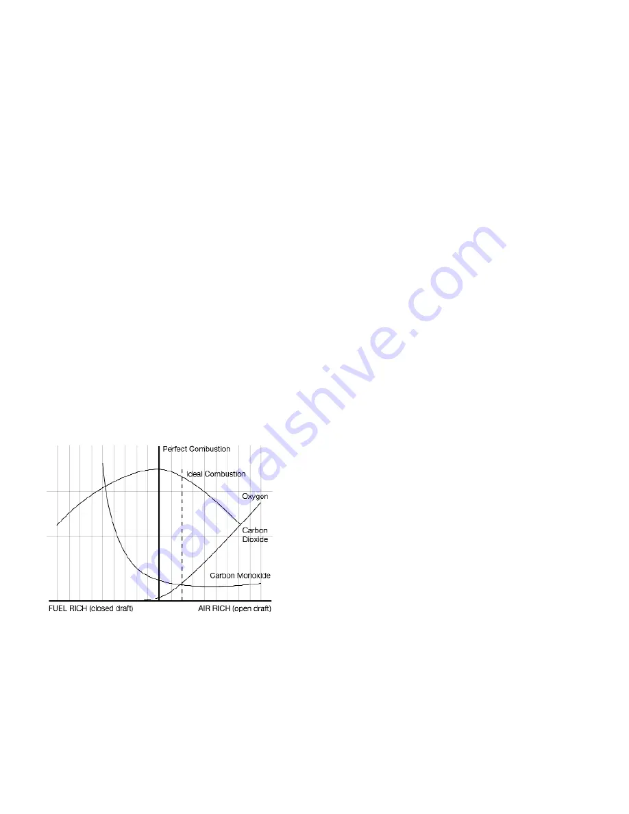
Below is a graph of typical combustion, showing the point of perfect
combustion and an approximate location for ideal combustion. You
will notice that by moving farther to the right on the air rich side (high
amounts of excess air), the pollutants (CO) don’t drop any further.
This is where you only lower efficiency. On the left side (fuel rich or
starved for air) you see a dramatic increase in carbon monoxide (CO),
indicating that a portion of the fuel is not being converted to heat.


