background image

                                                                                                                                                    UEBO S400 User Manual 

2-64 


WINS server

 refers to the IP address of the WINS server. After the WINS 

server is added, the


UEBO S400 can be accessed through the network name, 

Biso 

under the Windows client.   


Click 

OK

 to activate the CIFS after you finish the CIFS settings. The 

NAS 

setting

 interface is displayed a

fter the CIFS is activated. 

The modified information 

is displayed


NAS Setting 


Click 

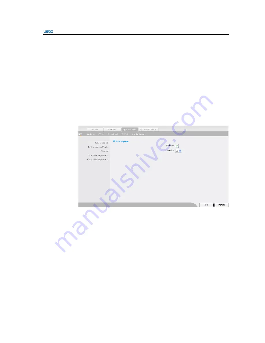
NFS Option

. The 

NFS Option 

interface is displayed. 

On this interface, you 

can activate or deactivate the NFS and select the NFS version

The maximum size 

of a file supported by V2 is 

32

 BIT. In addition, the

 -rsize

 and 

-wsize

 are used for 

the file transfer size and can be set to 

8

k only. Furthermore, V2 only supports the 

UDP. 


V3 supports the 64-bit file. No transfer size of the file is limited. In addition, 
V3 supports the UDP and TCP. 


Click 

OK 

after you set the NFS information. The NFS settings can be deactivated 

or activated. After that, the 

NAS setting

 interface is displayed. In addition, the 

modified NFS information is displayed.   

FTP Setting 


Содержание S400

Страница 1: ...UEBO S400 User Manual United Information Technology Co Ltd ...

Страница 2: ...ase feed back to us United Information Technology UIT Co Ltd reserves the right to revise the contents contained in this document if no notification is given Product Name UEBO S400 Manual Version 1 0 Delivery Date May 2010 Limited Warranty United Information Technology UIT Co Ltd ensures that all components of the UEBO S400 pass the all round test before delivery and function well under the common...

Страница 3: ...y attached guides of the UEBO S400 serial storage products are as follows Guide Name Contents UEBO S400 Hardware Installation and Maintenance Describes the features hardware structure installation and maintenance and cable connection UEBO S400 User Manual Provides the UEBO S400 configuration Conventions This document provides conventions in symbols keyboard operations mouse operations and safety s...

Страница 4: ...se the left mouse button quickly Double click Press the left mouse button twice continuously and quickly without moving the pointer Right click Press and release the right button quickly Drag Press and hold the left mouse button and move the pointer to a certain position Revision History Product Version Document Version Document No Description UEBO S400 V1 0 Initial draft ...

Страница 5: ... Shortcut 2 6 2 3 2 3 System Summary 2 33 2 3 3 System Options 2 34 2 3 3 1 Basic Options 2 34 2 3 3 2 Advanced Options 2 37 2 3 4 Devices 2 45 2 3 4 1 Disks 2 45 2 3 4 2 External Storage 2 57 2 3 4 3 External Wireless Interface 2 60 2 3 5 Applications 2 62 2 3 5 1 Network Storage NAS 2 62 2 3 5 2 Backup Volume 2 79 2 3 5 3 iSCSI 2 82 2 3 5 4 Download 2 86 2 3 5 5 DDNS 2 92 2 3 5 6 Media Server 2 ...

Страница 6: ...s 3 11 3 3 NAS Client Usage 3 14 3 3 1 Windows Client 3 14 3 3 2 Linux Client 3 21 3 3 3 Mac OS Client 3 23 Appendix A Acronyms and Abbreviations 1 Appendix B Guide for the Streaming File Production of the Darwin Streaming Server 2 ...

Страница 7: ...res such as embedded BT client software one touch copy and streaming service bring users a new storage experience Features The UEBO S400 uses the Power PC 460EX processor and DDR2 memory Therefore the product performance is improved The UEBO S400 is equipped with two 1 GB iSCSI host channels and transmits SCSI instructions and data over the Ethernet The UEBO S400 is with a small size and high capa...

Страница 8: ...dows Linux Unix and Mac OS Applicable Platform Windows Linux Unix and Mac OS Storage Media Disk Extension SATA channels Disk Quantity Up to four disks hot swap is not supported Storage Capacity Up to 8 TB Hard Disk Specifications See Hard Disk Compatibility List Management Functions Management Software UEBO Web Manager Storage Management System monitoring disk management RAID management virtual vo...

Страница 9: ...A Temperature 5 C 55 C Humidity 8 90 Dimension 196 mm W x 198 mm H x 165 mm D Weight 2 45 KG excluding the hard disk 1 4 Configuration Mode Description Due to the embedded management software of the UEBO S400 users can manage the storage through the Internet Explorer and use all the provided functions Network Topology ...

Страница 10: ...192 168 0 100 while the IP address of the eth2 is set to be the IP address obtained by the system automatically Connect the first network port to the Ethernet and ensure that the IP addresses of the client and UEBO S400 are at the same network port Start the UEBO S400 enter 192 168 0 100 and then log in to the UEBO Web Manager Login Interface The login interface of the UEBO Web Manager is as follo...

Страница 11: ...xe it does not need to be installed on the Client which is at the same network segment with the UEBO S400 Then click Refresh The following interface shows IP addresses of all the UEBO S400 which are at the same network segment with the client Choose an IP address in the interface and click access to access the login interface of the UEBO S400 ...

Страница 12: ... Then the following page is displayed 2 3 Option Instructions Objective Introduce functions usage and precautions of the options in the UEBO Web Manager page 2 3 1 Restart Logout and Close Restart Click on the upper right of the management page The UEBO S400 is restarted It costs one or two minutes ...

Страница 13: ...y Caution When closing the UEBO S400 ensure that the running program or device on the server does not use the UEBO S400 Otherwise service interruption and data loss may occur when the UEBO S400 is closed 2 3 2 Home 2 3 2 1 System Installation Disks Initialization Plug the disk in the UEBO S400 connect the first port to the Ethernet and enter the 192 168 0 100 in the IE bar of the client after the ...

Страница 14: ...File Click Next after the disk initialization is complete The Upload System File interface is displayed Select the system setup file in the setup directory in the CD ROM Click Upload System File S400_SysOS_1 0 Build12817 tar gz after the setup file is selected Click Next after the setup file is uploaded ...

Страница 15: ... in the IE bar of the client Log in to the system with the user name admin and password 123456 2 3 2 2 Shortcut The Shortcut option provides the shortcut setting mode of the common functions The Shortcut option covers the following modules Quick Setting System Status Disk Groups Virtual Partition Shares iSCSI Management Users Management and Groups Management ...

Страница 16: ...le provides a shortcut mode of setting the UEBO S400 You can finish the setting based on the following method Click Quick Setting icon The following interface is displayed Click Next to set the system name The System Name Option interface is displayed ...

Страница 17: ... Click Next after setting the system name The Rote Access Option interface is displayed If you want to cancel the current settings click Previous to go to the upper level interface Select Activate SSH and specify the Web port number Caution 1 The default port number of the SSH is 22 The maximum port number entered must not exceed 65535 ...

Страница 18: ...rent settings click Previous to go to the upper level interface Click Next after setting the Service Control option The Network interface is displayed On the Network interface you can finish the network configuration If you want to cancel the current settings click Previous to go to the upper level interface Click Next after setting the Network option The Finish Quick Setup interface is displayed ...

Страница 19: ...he System Status interface is displayed Disk Groups The Disk Groups module provides a shortcut mode of the disk group management On this interface you can create expand and delete the disk groups Create Disk Groups Click Create The Disk Group Type interface is displayed Select the type of the disk group to be created The UEBO S400 supports the following types RAID0 RAID1 RAID5 and JBOD ...

Страница 20: ...ick Next after selecting the corresponding RAID type The Disk List interface is displayed Select the disks used for creating the disk group Click Next after selecting the disks The Disk Group Creation Preview interface is displayed ...

Страница 21: ...Manual 2 12 Click Create to finish the creation of the disk group Expand Disk Groups Click Expand beside the disk group to be expanded on the Disk Group List interface The Disk Group Information interface is displayed ...

Страница 22: ...ick Next An interface of the disk list is displayed Select the free disks and click Next to expand the disk group The Disk Group Expand Information interface is displayed Click Start expans to finish the expansion of the disk group ...

Страница 23: ...ent only the JBOD type supports the disk group expansion Remove Disk Groups Click Disk Groups Management The Disk Group List interface is displayed Click Remove beside the disk group to be removed The Remove disk group preview interface is displayed The information about the disk group to be removed is listed ...

Страница 24: ...e removed Then click Remove to delete the disk group Virtual Partition The Virtual Partition module provides a shortcut mode of the virtual partition management You can create expand and remove the virtual partition Click Virtual Partition icon The Virtual Partition List interface is displayed Create Virtual Partitions Click Create The Select Disk Group interface is displayed Select the correspond...

Страница 25: ...xt after selecting the disk group The Virtual Partition Information interface is displayed Set the name and capacity Click Next after setting the virtual partition information The Virtual Partition Creation Preview interface is displayed ...

Страница 26: ... the virtual partition creation starts Expand Virtual Partitions Click Expand beside the virtual partition to be expanded after the Virtual Partition List interface is displayed Then the Expand Virtual Partition interface is displayed Click Next after entering the new capacity Caution 1 The value entered must be less than the available capacity of the current disk group ...

Страница 27: ...pecify whether the expansion information about the virtual partition is correct If the expansion information about the virtual partition is correct click Expand Directory Remove Virtual Partitions Click Remove beside the virtual partition after the Virtual Partition List interface is displayed Caution If the virtual partition is active you can not remove it unless all relevant applications are rem...

Страница 28: ... virtual partition cannot be removed Shares This Shares module provides a shortcut mode for the directory sharing In addition the module supports the following operations create format remount and delete shares Caution In the list characters in different colors show different status of services in the NAS 1 Gray Services are unavailable 2 Red Services are activated without any configuration 3 Gree...

Страница 29: ...he Virtual Partition Manager page to create a virtual partition Click Confirm to create a share If the share is created successfully the NAS Share Directory List interface is displayed You can view the created share in the NAS Share Directory List interface Format Shares Click Shares The NAS Share Directory List interface is displayed Click Format beside the share to be formatted A dialog box is d...

Страница 30: ...e the share to be deleted A dialog box is displayed Click OK to delete the share The NAS Share Directory List interface is displayed after the share is deleted In addition the relevant data saved on the share is deleted iSCSI Management This iSCSI management module provides a shortcut mode of the iSCSI management In addition the module supports the following operations create close edit and delete...

Страница 31: ...I interface is displayed Select the virtual partition in the Virtual Partition drop down list box To pen the CHAP access right click Confirm after the User Name and Password is set Otherwise the Add iSCSI interface is displayed if you click Confirm directly ...

Страница 32: ...ual partition list is null go to the Virtual Partition Manager page to create a virtual partition After an iSCSI is added successfully the iSCSI List interface is displayed In addition you can view the created iSCSI in the iSCSI List interface Close an iSCSI Click iSCSI Management The iSCSI List interface is displayed Click Close beside the iSCS to be closed ...

Страница 33: ...splayed To open the iSCSI click Open Edit an iSCSI Click iSCSI Management The iSCSI List interface is displayed Click Edit beside the iSCSI to be edited The Modify iSCSI interface is displayed On this interface you can modify the CHAP type If the CHAP access right is opened you can modify the value of the User Name and Password ...

Страница 34: ...splayed The deleted iSCSI is not displayed in the iSCSI List interface Users Management The module provides a shortcut mode of the user management In addition the module supports the following operations create and delete users assign groups and change the user password Caution 1 The administrator user admin belongs to the administrators group by default 2 The added users belong to everybody group...

Страница 35: ...assword and select Assign user groups Caution The length of the user name for the nas is 1 32 digits while the length of the password is 6 20 digits including numbers or letters 1 If you select Default click Confirm to add a user The User List interface is displayed after the user is added successfully ...

Страница 36: ...sign Group interface is displayed On this interface you can add a specific group After that click Confirm to add a user group After the user group is added successfully the User List interface is displayed In addition you can view the newly added user group in the User List interface ...

Страница 37: ...al 2 28 Assign User Groups Click Users Management The User List interface is displayed You can assign a user group for already users Click Assign Group beside the user to be edited The Assign Group interface is displayed ...

Страница 38: ...up is modified successfully the User List interface is displayed The modified information is displayed under the Group Name Change Password Click Users Management The User List interface is displayed Click Change Password beside the user to be modified The Change Password interface is displayed Enter the new password and confirm it ...

Страница 39: ...e deleted A dialog box is displayed as follows Click OK to delete the specific users After the users are deleted successfully the NAS User List interface is displayed In addition the deleted users are not displayed in the User List interface Groups Management The module provides a shortcut mode of the group management In addition the module supports the following operations add assign and delete g...

Страница 40: ...dd Group The Add Group interface is displayed Enter a group name and click Confirm After the group is added successfully the NAS Group List interface is displayed In addition you can view the added group in the NAS Group List interface ...

Страница 41: ...e group name can not be numbers only Assign Users Click Groups Management The NAS Group List interface is displayed Click Assign User The Assign User interface is displayed Click Confirm after selecting the specific users The NAS Group List interface is displayed after assigning users successfully In addition the modified information is displayed under the User Name ...

Страница 42: ... dialog box is displayed Click OK to delete users The NAS Group List interface is displayed after the group is deleted successfully In addition the deleted group is not displayed in the NAS Group List interface 2 3 2 3 System Summary System Summary Through the System Summary option you can query the system information device status and service status ...

Страница 43: ...rface is displayed On this interface you can set the system name The characters entered must be numbers letters and underscores In addition the length must not exceed 32 digits Remote Login Choose Basic Options Remote Login The Remote Access Option interface is displayed On this interface you can activate the SSH and enter the Web port number ...

Страница 44: ...he Administrator interface is displayed On this interface you can set the user name and password the length of the password ranges from 6 to 20 digits Date and Time Choose Basic Options Date and Time The Date and Time interface is displayed On this interface you can set the date and time In addition you can select the time zone of various cities in the world Furthermore you can select the date and...

Страница 45: ...me 3 if the preceding two methods are not selected the date and time can be set manually Network Choose Basic Options Network The Network interface is displayed On this interface you can set the network of the UEBO S400 In addition three network modes are provided as follows Failover Load balancing and Standalone You can select the corresponding network mode The three network modes support the fol...

Страница 46: ...2 Ensure that the network IP address and the gateway IP address are at the same network segment and are set correctly Otherwise the whole network is disabled 3 Ensure that only a DHCP IP address is set between the two network ports when selecting the Standalone network mode 2 3 3 2 Advanced Options System Status Choose Advance Options System Status The System Status interface is displayed On this ...

Страница 47: ...e and send the email notification based on the log level The log level is as follows Normal notification and error Caution 1 Log level setting indicates that the log information of a specified level will be saved to a corresponding log when the operation faults occur 2 If you activated the email notification the log information of a specified level will be sent to the specified mailbox and saved t...

Страница 48: ...ick Test Mail after setting the email notification If the mailbox of the entered email address receives the emails sent by the system it indicates that the email notification setting is successful System Logs Choose Advance Options System Logs The System Logs interface is displayed On this interface you can select the display type to view the logs The type includes three modes as follows Normal no...

Страница 49: ...m Diagnose interface is displayed On this interface you can diagnose the system Backup Restore Settings Choose Advance Options Backup Restore Settings The Backup Restore Settings interface is displayed On this interface you can back up and restore the settings and restore the default settings ...

Страница 50: ... S400 User Manual 2 41 Click Backup The File Download dialog box is displayed Click Save to save the file Restore Settings Click Browse select the file backed up and click Restore A dialog box is displayed ...

Страница 51: ...r Manual 2 42 Click OK The settings are restored Refresh the interface after restoring the settings Then the last backup time is displayed You can restore the default settings Click Restore A dialog box is displayed ...

Страница 52: ... services such as iSCSI and NAS time zone Web ports and data and time setting are restored to the default settings 2 Be cautious when restoring the default settings System Upgrade Choose Advance Options System Upgrade The System Upgrade interface is displayed On this interface you can upgrade the system to a new version Click Browse to select the upgrade package Click Update to and ensure that the...

Страница 53: ...e information about the System Summary Application Extend Choose Advance Options Application Extend The Application Extend interface is displayed On this interface you can extend the applications Click upload after selecting the application expansion pack Then a dialog box is displayed Click OK to finish the upload process After that you can install and delete the application expansion pack ...

Страница 54: ...Scan disks fast and completely 2 Create expand restore and remove disk groups 3 Create expand restore and delete the virtual partition 4 Query USB storage status 5 one touch copy and connect the wireless network 2 3 4 1 Disks Disks Status Choose Disks Disks Status The Disk List interface is displayed On this interface you can query the disk property and scan the disk completely and quickly ...

Страница 55: ...sk is scanned completely During the scanning the Stop Scan button is provided for stopping the scanning process at any time If the full scan costs a long time you can click Stop Scan to stop the scanning process Click Stop Scan The scanning process is stopped Quick Scan Click Quick Scan beside a disk to scan the disk quickly Click Stop Scan The scanning process is stopped Disk Groups ...

Страница 56: ...k Group Click Create An interface for selecting a disk group is displayed Click Next after selecting the type of the disk group The Disk List interface is displayed Select disks used by the disk group The required quantity of free disks verifies with the RAID level In addition the RAID0 and RAID1 require three disks at least independently the RAID5 requires four disks at least the JBOD require two...

Страница 57: ...sks The Disk Group Creation Preview interface is displayed Click Create to create a new disk group The Disk Group List interface is displayed after the disk group is created successfully In addition the created disk group is displayed in the Disk List interface ...

Страница 58: ...e are not lost but their security is lowered click Repair to repair the disk group when the free disks with the same capacity exist The security of the RAID data and the relevant file can be improved through the repairing the RAID Caution Do not plug in the eSATA devices when repairing the RAID Expand a Disk Group ...

Страница 59: ... interface is displayed Caution The JBOD type disk group can be expanded only Click Next The Disk List interface is displayed Select the disks used by the disk group to be expanded Click Next after selecting the disks of free status The Disk Group Expand Information interface is displayed ...

Страница 60: ...ist interface is displayed after the disk group is expanded successfully In addition the information about the expanded disk group is displayed on this interface Remove a Disk Group Click Remove beside the disk group to be removed The Remove Disk Group Preview interface is displayed ...

Страница 61: ...ns under the disk group must be deleted before the disk group is removed 2 Removing the disk group may cause the data loss of the disk group Therefore be cautious when implementing this operation Virtual Partition Choose Disks Virtual Partition The Virtual Partition interface is displayed The interface supports the following operations 1 Query the information about all virtual partitions 2 Create ...

Страница 62: ...k Group Select interface is displayed Click Next after you select the disk group consisting of the virtual partition The Virtual Partition Information interface is displayed Set the name and capacity of the virtual partition the capacity must not exceed the available capacity of the disk group ...

Страница 63: ...interface is displayed Click Create to create a virtual partition after you ensure that the information is correct The Virtual Partition List interface is displayed after the virtual partition is created successfully The created virtual partition is displayed on this interface ...

Страница 64: ... 2 55 Expand a Virtual Partition Click Expand beside the virtual partition The Expand Virtual Partition interface is displayed Enter the new capacity Click Next The Virtual Partition Expansion Preview interface is displayed ...

Страница 65: ...orrect The Virtual Partition List interface is displayed after the virtual partition is expanded successfully The modified information about the expanded virtual partition is displayed Remove Virtual Partitions Click Remove beside the virtual partition to be removed The Virtual Partition Remove Preview interface is displayed ...

Страница 66: ... virtual partition may cause its data loss Therefore be cautious when implementing this operation Click Remove to remove the virtual partition after you ensure that the information is correct The Virtual Partition List interface is displayed after the virtual partition is removed successfully The removed virtual partition is not displayed on this interface 2 3 4 2 External Storage Device Status ...

Страница 67: ...evices is displayed Click Format The Select File System interface is displayed The file system includes the following format types XFS FAT32 EXT2 and EXT3 Click Next to continue Data copy Select Data copy The Data copy interface is displayed On this interface you can copy the data of the external device Select a share created previously If you want to copy all the data select copy all file check b...

Страница 68: ...he nas test directory One Touch Copy Option Choose Devices External Storage Then you can view the Device Status and One Touch Copy Option Click One Touch Copy Option The One Touch Copy Option interface is displayed On this interface you can select the saved directory create a new directory and set the copy type Click Save to save the settings Click One Touch Copy Option on the front panel The sele...

Страница 69: ...CIFS setting of the NAS if the one touch copy file is displayed as illegible characters 2 3 4 3 External Wireless Interface Wireless Network Sites Choose Devices External Wireless Interface On this pane you can view the information about the wireless network sites When no wireless network card is plugged in the external wireless interface a message Wireless LAN is not detected is displayed After y...

Страница 70: ...work card connection select it based on the authentication mode of the wireless network The wireless authentication mode covers the following mode OPEN WEP WPA PSK and WPA2 PSK Enter the value of the Key and set the IP Setting Click connect after you finish the settings Then you can view that the wireless network site is connected red ...

Страница 71: ... following modules NAS Backup iSCSI Download DDNS and Media Server 2 3 5 1 Network Storage NAS NAS Setting Choose Applications NAS Options The NAS setting interface is displayed On this interface you can query and set the status of the CIFS NFS FTP and AFP these protocols are deactivated by default After four protocols are activated the status of each protocol is active green In this case the UEBO...

Страница 72: ...ng Click CIFS Option The CIFS Option interface is displayed On this interface you can activate or deactivate the CIFS Select Activate and set the relevant information NetBiosName refers to the name the system name that the UEBO S400 can identify in the network Workgroup refers to the group where the UEBO S400 is DOS charset and Unix charset refer to the file codes under the Window and Linux respec...

Страница 73: ...ion interface is displayed On this interface you can activate or deactivate the NFS and select the NFS version The maximum size of a file supported by V2 is 32 BIT In addition the rsize and wsize are used for the file transfer size and can be set to 8k only Furthermore V2 only supports the UDP V3 supports the 64 bit file No transfer size of the file is limited In addition V3 supports the UDP and T...

Страница 74: ...The user name and password are not required when the client access is implemented Maximum number of all FTP connections It refers to the maximum number of clients Maximum number of connections for a single account It refers to the maximum number of clients sharing a single account Click OK to activate the FTP after you finish the FTP settings The NAS setting interface is displayed after the FTP is...

Страница 75: ...d password When the AFP mode is Guest no user name and password is required MAC coding Two modes are provided LOCALE and MAC_ROMAN Unix coding Two modes are provided LOCALE and ASCII When the client reads a file and the illegible characters occur you can modify the MAC coding mode to another mode Max clients It refers to the maximum number of clients that can be connected Click OK to activate the ...

Страница 76: ...he Windows domain when the shares are accessed Share The shares can be accessed without a user name and password Caution 1 When you select Active Directory ensure that the time zone of the system is the same as the domain server In addition the time difference must not exceed five minutes and t he domain name must be capitalized letter 2 The authentication mode is valid only for the CIFS Click OK ...

Страница 77: ...t interface The Create share interface is interface Select the virtual partition Click OK after you select the virtual partition The share is created The NAS share list interface is displayed after the share is created successfully The created share is displayed on the interface ...

Страница 78: ...er Manual 2 69 Format a Share Click Format beside the share to be formatted A dialog box is displayed Click OK to format the share The NAS share list interface is displayed after the share is formatted successfully ...

Страница 79: ...d A dialog box is displayed Click OK to delete the share The NAS share list interface is displayed after the share is deleted successfully The deleted share is not displayed in the NAS share list Remount a Share Click Remount to mount the share again if the share fails to be remounted ...

Страница 80: ...assign user groups change password and delete users Create a User Click Users Management The User List interface is displayed Click Add user The Add user interface is displayed Set the User Name and Password and select the group which the user belongs to Select Default and click OK to add a user The User List interface is displayed after the user is added successfully ...

Страница 81: ...UEBO S400 User Manual 2 72 Select a specified group and click OK The Assign groups interface is displayed On this interface you can add a specific group ...

Страница 82: ...layed after the user is created successfully In addition the created user is displayed on this interface Assign a User Group Click Users Management The User List interface is displayed You can assign a user group for the existing users Click Assign groups beside a user The Assign groups interface is displayed ...

Страница 83: ...or remove a specific group The User List interface is displayed after the settings are modified successfully Change Password Click Users Management The User List interface is displayed Click Chang Password beside a user The Chang Password interface is displayed Enter the new password ...

Страница 84: ...Delete a Specific User Click Users Management The NAS User List interface is displayed Click Delete beside a user A dialog box is displayed Click OK to delete the specific user The User List interface is displayed after the specific user is deleted successfully The deleted user is not displayed on this interface ...

Страница 85: ...strators and everybody group cannot be removed The administrators group is a group which has the administrator permission while the everybody group is a group has the most common and convenient permission In addition each user belongs to the everybody group and has the read write authority by default Add a Group Click Groups Management The NAS Group List interface is displayed Click Add group The ...

Страница 86: ...p List interface is displayed after the group is added successfully The added group is displayed in this interface Assign Users Click Groups Management The NAS Group List interface is displayed Click Assign Users beside a user group The Assign Users interface is displayed ...

Страница 87: ...up List interface is displayed after users are assigned successfully In addition the modified information about users is displayed under the User Name Delete a User Group Click Groups Management The NAS Group List interface is displayed Click Delete beside the group to be deleted A dialog box is displayed ...

Страница 88: ... deleted successfully 2 3 5 2 Backup Volume Backup Volume Choose Applications Backup Backup Volume Mgt The Backup Volume List interface is displayed All information about the backup volume in the UEBO S400 is displayed on this interface The following operations are supported Create remount format and delete backup volumes ...

Страница 89: ...ion Caution If the virtual partition list is null go to the Virtual Partition Manager page to create a virtual partition Click OK to add a backup volume after you select a virtual partition The Backup volume list interface is displayed after the backup volume is added successfully The added backup volume is displayed on this interface ...

Страница 90: ...me Click Format beside a backup volume to be formatted on the Backup volume list interface A dialog box is displayed Click OK to format the backup volume The Backup volume list interface is displayed after the backup volume is formatted successfully ...

Страница 91: ...splayed Click OK to delete the backup volume The Backup volume list interface is displayed after the backup volume is deleted successfully The deleted backup volume is not displayed on this interface 2 3 5 3 iSCSI Choose Applications iSCSI The iSCSI module supports the following operations Set and query the iSCSI status activate edit and delete an iSCSI ...

Страница 92: ...ing Click iSCSI Setting The iSCSI Setting module supports the following operations 1 Query the iSCSI status 2 Activate and deactivate the iSCSI To deactivate an iSCSI click Deactivate on the iSCSI status interface A dialog box is displayed ...

Страница 93: ...UEBO S400 User Manual 2 84 Click OK to deactivate the iSCSI service After that the iSCSI status interface is displayed The iSCSI is deactivated ...

Страница 94: ...le supports the following operations Close edit and delete an existing iSCSI Click Edit to modify the iSCSI permission The Modify iSCSI interface is displayed Set the user name and password Caution The length of the user name for the CHAP authentication ranges from 1 to 32 digits while the length of the password ranges from 6 to 20 digits including numbers or letters ...

Страница 95: ... select the download mode and set the relevant parameters Download Setting Step 1 Choose Applications Download Download Setting The Download Setting interface is displayed On this interface you can select Enable HTTP FTP Download or Enable BT Download To enable a certain download mode select the relevant check box and click Save ...

Страница 96: ...400 User Manual 2 87 Step 2 Select a share at least before saving the download settings Then click Create share Select a virtual partition as the share and click OK The created directory is added to the share ...

Страница 97: ...he FTP HTTP download interface is displayed On this interface you can view the information about a running task In addition you can add a new task stop a task view the completed tasks and set the download Step 2 Add a new FTP HTTP task Click Add new task and enter the URL downloaded in the dialog box ...

Страница 98: ...the download process In this case the status size download percent rate and left time are displayed on the FTP HTTP download interface In Addition you can pause and delete the task and view the property of the task Step 4 View the paused task as follows ...

Страница 99: ...ks Step 6 Click Set Config to set the maximum number of the tasks at the same time maximum download rate and the network share folder End The maximum number of the tasks at the same time is 10 BT Download Step 1 Click the following link to enter the BT Download Station after the BT download service is stated ...

Страница 100: ...UEBO S400 User Manual 2 91 Step 2 Add a torrent Click Browse to add the torrent and click Upload file Step 3 Query the download information End ...

Страница 101: ...the DDNS PeanutHull and http www 3322 org You need to register in the PeanutHull and http www 3322 org first DDNS Setting Activate the DDNS and select the DDNS service provider Enter the registration information about the DDNS Click Save to finish the DDNS settings ...

Страница 102: ...create a share folder to save the media files In addition upload the media files to the share folder before using these files Media Server Setting Step 1 Set a media file path Based on the previous introduction choose Applications Media Server Media Server Setting Select a share in the Media File path drop down list box and click Save Click Media Server Web Manager Log in to the streaming server w...

Страница 103: ...Step 2 Add a new media playlist The Web management page of the streaming server is displayed after you click Media Server Web Manager Click New Media Playlist as shown in the preceding figure The following interface is displayed ...

Страница 104: ...ag the media files from the left to the right playlist and click Save Then the media playlist is set up Step 3 Enable the media playlist According to the following figure click Main and then Playlist In this case the playlist is available Step 4 Test the play situations of the media files Enter an URL to open the media file through the Apple QuickTime End ...

Страница 105: ...BO backup software which is seamlessly integrated in the UEBO S400 provides dual protection for the user data In addition the UEBO backup supports the data increment backup and compression backup Moreover the UEBO backup supports the backup and restoration of multiple clients at the same time To use UEBO backup software add a new backup volume to the UEBO S400 server to store the backup data UEBO ...

Страница 106: ... of the client The following folders are provided xp corresponding to the Windows XP operating system win7 corresponding to operating system of the Vista Windows 7 and Windows server 2008 For the Windows 7 install the vcredist_x86 exe Then install the setup_win7 exe Right click the blank area You can view that the following two menu items are added Backup to UEBO B UEBO Backup tool U ...

Страница 107: ... click the blank area and then choose UEBO Backup tool Modify login setting After that you can enter or search the IP address of the server The default value of the User Name is admin while the default value of the Password is 123456 Note The admin is inerasable ...

Страница 108: ...a Right click the blank area and choose UEBO Backup tool System set S to display the system set interface Then Click System Management to set the backup data path and click Browse to select the preceding added backup volume Finally click ok to finish the settings ...

Страница 109: ... the senior backup Right click a file or folder and choose UEBO Backup tool back up to UEBO advanced option Two backup modes are provided normal backup and increment backup In addition the increment backup indicates that the system only backs up the changed contents after the previous backup The backup option supports four operations 1 Compress the backup data 2 Delete the source data after the ba...

Страница 110: ...ckup description option identifies the backup for easy search Step 7 Restore backup records Right click the blank area and chose UEBO Backup tool restore to restore the data All backup records of the system are displayed Therefore select the record to be restored ...

Страница 111: ...UEBO S400 User Manual 2 102 ...

Страница 112: ...UEBO S400 User Manual 2 103 ...

Страница 113: ...ive This chapter describes the basic methods of connecting the UEBO S400 with the iSCSI initiator software in the Windows and Linux scenarios 3 2 1 Windows Host Scenarios Description The host uses the Windows operating system iSCSI initiator software version is MS initiator2 06 or later version Operation Process Step 1 Download the latest iSCSI initiator software in the Microsoft website A shortcu...

Страница 114: ...400 User Manual 3 2 Step 2 Double click the Microsoft iSCSI Initiator icon and click Discovery Click Add to add the IP address of the UEBO S400 The default port number is 3260 as shown in the following figure ...

Страница 115: ...UEBO S400 User Manual 3 3 Step 3 Click Advanced Then you can select Local adapter and Source IP In addition you can select the default value ...

Страница 116: ...UEBO S400 User Manual 3 4 Step 4 Click OK to complete the settings of the Add target portal interface ...

Страница 117: ...UEBO S400 User Manual 3 5 Step 5 Click Targets The iSCSI Initiator Properties interface is displayed Then click Refresh ...

Страница 118: ...UEBO S400 User Manual 3 6 Step 6 View that the status of the current target is inactive ...

Страница 119: ... box indicates that the connection restores automatically when the system is restarted Selecting the second check box indicates that the multi path is enabled When more than two input output IO paths exist between the host and the UEBO S400 the reliability and performance are improved through the multi path function ...

Страница 120: ...UEBO S400 User Manual 3 8 Step 8 Click Advanced to add multiple Source IP and Target Portal on the Log On to Target interface ...

Страница 121: ...UEBO S400 User Manual 3 9 Step 9 Click OK to finish the host connection ...

Страница 122: ...anagement to scan the disk again The virtual partition of the connected UEBO S400 is found When the CHAP authentification exists follow Step 1 to Step 7 In the Step 8 select CHAP logon information enter the user name and password and then click OK After that follow Step 9 and Step 10 ...

Страница 123: ...ser Manual 3 11 3 2 2 Linux Host Scenarios Operation Process The IP address of the system involved in the following operations is supposed to be 172 16 96 2 View the iSCSI volume through the Web client as follows ...

Страница 124: ...hentication exists run the following three commands suppose that the user name is test and the password is 123456789123 Then follow Step 5 Run the following command to modify the CHAP authentication iscsiadm m node p 172 19 62 88 T iqn 2007 10 com 415154837raid5 iscsi n node session auth au837raid5 iscsi n node session auth authmethod v CHAP o update Run the following command to modify the user na...

Страница 125: ... the iSCSI volume is connected Then you can view that the Disk dev sdb connected to the iSCSI volume directory is added as follows 5 Run the following command to disconnect the iSCSI volume iscsiadm m node p 172 16 96 2 T iqn 2007 10 uit com 22124056raid1 iscsi u Then run the fdisk 1 command The previous Disk dev sdb directory does not exist For details refer to the following figure ...

Страница 126: ...3 3 1 Windows Client Operation Process Two NAS of the CIF and FTP under the Windows client are introduced CIFS Step 1 Activate the CIFS setting of theUEBO S400 and enter the relevant information Step 2 Add a group in the NAS setting of the UEBO S400 ...

Страница 127: ...UEBO S400 User Manual 3 15 Step 3 Add a new user user name test01 and the password password under the Users Management module Step 4 Create a share ...

Страница 128: ...cess right of the users are not set the access right of the users are subject to the access right of the groups When the access right of the groups are not set while the access right of the users are not set the access right of the users are subject to the set access right of the users When the access right of the users and groups are set the read write authority is first ...

Страница 129: ...Step 6 Choose Start Run and enter the IP address of the UEBO S400 on the Window client Step 7 Enter the user name and password involved in Step 5 and click OK Step 8 Implement the relevant operations of the share based on Step 5 ...

Страница 130: ...UEBO S400 User Manual 3 18 FTP Step 1 Activate the FTP settings of the UEBO S400 and modify the relevant parameters Step 2 Add a group in the NAS setting of the UEBO S400 ...

Страница 131: ...UEBO S400 User Manual 3 19 Step 3 Add a new user user name test01 and the password 123456 under the Groups Management module Step 4 Create a share ...

Страница 132: ...users and group based on the created share involved in Step 4 Step 6 Enter ftp UEBO S400 ip in the Internet Explorer IE address bar and press Enter A dialog box is displayed Then enter the user name and password The FTP share is displayed after the authentication ...

Страница 133: ...illip user UID 1051 The share name is documents and the virtual disk name is Shenzhen The NFS access right is set to be 192 168 17 0 24 The read write authority is supported by the UEBO S400 within the network segment The IP address of the UEBO S400 is 192 168 17 50 Linux Client Accessing the NFX Share 1 Run the showmount command on the Linux client to list the NFS share on the UEBO S400 root loca...

Страница 134: ...host c root localhost c echo 0 4 Uninstall the NFS share root localhost c cd root localhost umount mnt c Linux Client Accessing the CIFS Share 5 Connect the CIFS share and then enter the user name Philip and its password root localhost mount t CIFS o username phillip 192 168 17 50 share shenzhen documents mnt c Password 6 Read write and delete the data in the CIFS share root localhost cd mnt c roo...

Страница 135: ...Description The system version of the host is Mac OS 10 4 6 X86 Operation Process 1 Activate the AFP setting of the UEBO S400 and set the relevant parameters 2 Create a group in the NAS setting interface of the UEBO S400 3 Add a new user tester01 and its password Groups Management module ...

Страница 136: ...UEBO S400 User Manual 3 24 4 Create a share 5 Set the access right of the users and group ...

Страница 137: ...Manual 3 25 6 Enter afp UEBO S400 ip in the safari browser on the Mac OS client and press Enter Then enter the user name and password in the displayed dialogue box 7 Click Connect to choose the AFP directory to be set ...

Страница 138: ...UEBO S400 User Manual 3 26 The directory cannot be used until the icon of the AFP directory is set up on the desktop ...

Страница 139: ... of the SCSI instruction and data based on the current Ethernet CIFS The CIFS is an operation mechanism of the open cross platform for client system to require the files and printing service to the server NFS Network File System DAS Direct Attached Storage SAN Storage Area Networking NAS Network Attached Storage JBOD Just Bundle of Disks RAID Redundant Array of Independent Disks LED Light emitting...

Страница 140: ... the hint processing of the video file must be implemented For example the video file is distributed as the flow mode on the streaming server Take the production process of the streaming files for example 8 Hint processing instructions for the video file supported by the Darwin streaming server Instructions The Apple QuickTime Pro supports the function of exporting the media file as the streaming ...

Страница 141: ... Select the source file Save the file as the self contained movie ...

Страница 142: ... Select the saving type as the self contained movie Export the movie to the file of the mov format Select the exporting type of the movie as the Movie to Quick Time Movie and select Default Settings ...

Страница 143: ...nversion Steaming mp4 files production Open the mov file Select the source file Save the file as the self contained movie Select the saving type as the self contained movie Export the movie as a movie of the mp4 format ...

Страница 144: ...t parameter values according to the actual needs but ensure that the streaming is enabled for details of the settings refer to the following figure The following figure is only an example for the settings of the minor modification most of the parameters use the default values of the software a File Format Setting Select MP4 ...

Страница 145: ...g Select MPEG 4 Improved as the video format Select Current as the value of the Image Size Maintain the default values of other parameters You can adjust the parameter values if the video quality is bad after the conversion ...

Страница 146: ...c Audio Format Setting Adopt the default setting d Streaming Setting ...

Страница 147: ...timizing the server Click OK to convert the format Note Converting the self contained mov file to the streaming mp4 file costs more time than converting to the mov file In addition the quality of the movie sources is more excellent The lower capacity of the PC costs more time Moreover when the file is distributed in streaming mode after the conversion the quality of the video is affected ...

Страница 148: ...es production Open the mov file Select the source file Save the file as the self contained movie Select the saving type as the self contained movie Export the file as the 3gp file Select Movie to 3G as the exporting type ...

Страница 149: ...o the actual needs but ensure that the streaming is enabled for details of the settings refer to the following figure The following figure is only an example for the settings of the minor modification most of the parameters use the default values of the software a File Format Setting Select 3GPP ...

Страница 150: ...b Video Format Setting Select MPEG 4 Select Current as the value of the Image Size and Frame Rate and maintain the default values of other parameters ...

Страница 151: ...c Audio Format Setting Adopt the default setting d Text Setting ...

Страница 152: ...e Streaming Setting Select Enable streaming check box You can select or clear Optimize for server check box based on the requirements The Optimize for server check box is not selected by default namely not optimizing the server ...

Страница 153: ...f Advanced Setting Adopt the default setting ...

Страница 154: ...e costs more time than converting to the mov file In addition the quality of the movie sources is more excellent The lower capacity of the PC costs more time Moreover when the file is distributed in streaming mode after the conversion the quality of the video image and frame rate is affected ...

Страница 155: ... END ...

Отзывы: