


18
Figure 17. Browse file menu
8.
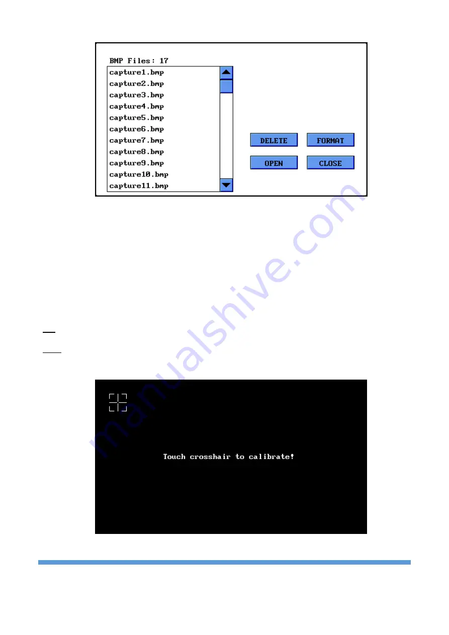
Screen Calibration
When a more precise touch is needed, you may do touch panel calibration. To do this click ‘Screen
Calibration’ and pass to the following display. Press in the middle of crosshair icon on the display with the
pen. After
four points, if the calibration is successful, the ‘smiley face’ symbol appears on the display and
the program returns to settings menu. If the calibration is unsuccessful, the program prompts you to go
back and repeat calibration.
Tip: Use medium touches instead of soft ones during calibration.
Note: After updating software, screen calibration is required again. Right after the updating, in the first
start-up, the screen calibration menu appears automatically.
Figure 18. Screen Calibration


