EVK-IRIS-W10 - User guide
UBX-23007837 - R03
Hardware description
Page 21 of 43
C1-Public
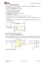
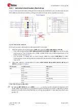
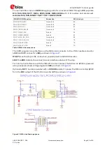
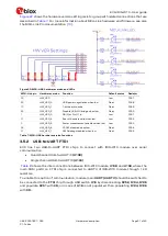
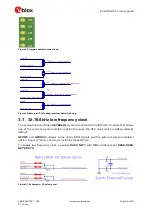
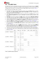
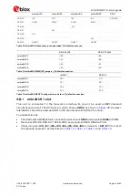
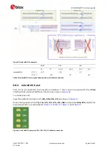
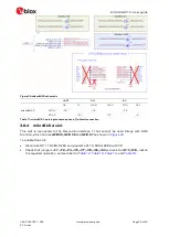
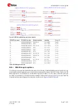
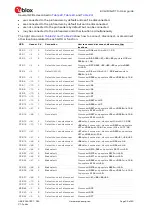
shows the hardware version setting resistor group with related connections that are
For more information about MCU-Link hardware and firmware, see also
the MCU-Link Pro documentation
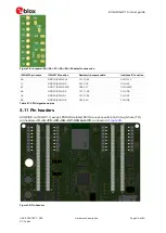
Figure 22: MCU-LINK hardware version and LEDs
MCU-Link pin
Hardware version
Function
Default status
Resistor
55
HW_VER
-
Low
R187
85
HW_VER_0
USB power negotiation when low
Float
R188
73
HW_VER_1
1-bit board id code
Float
R189
65
HW_VER_2
Disable USB-SIO bridge when low
Float
R190
1
HW_VER_3
OB(0) or Pro (1) id
Low
R191
31
HW_VER_4
Board id code is valid when low
Low
R192
5
HW_VER_5
Power measurement enabled when low
Low
R193
56
HW_VER_6
VCOM disabled when low
Float
R194
27
HW_VER_7
SWD debug disabled when low
Float
R195
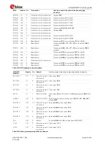
Table 7: MCU-LINK hardware version functions
3.5.2
USB-to-UART FTDI
EVK has two USB-to-UART FTDI chips to connect with IRIS-W10 module over serial
communication.
•
Quad channel USB-to-UART IC
(U108)
•
Single channel
USB-to-UART IC
(U109)
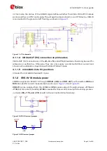
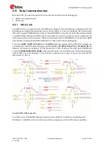
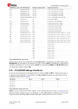
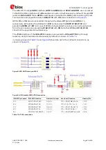
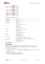
shows the inter connections between IRIS-W10 module,
U108
, and
U109
, where the
main COM port3 on FTDI chip is connected to UART3 of IRIS-W10 module through 1 k
Ω
resistors.
To enable this option of communication, module main
UART (UART 3)
should be switched to
be connected to the
FTDI
chip
through USB switch
U16
by disconnecting
R252, R134, R136
and populate
R251
with
0R,
or in case of
U16
is not populated,
then populating
R134, R136
with
0R.

