


EVK-MAYA-W2 - User guide
UBX-22011269 - R04
Board description
Page 12 of 20
C1 – Public
provides a summary of the connectors and pin headers shown in
Designator
Function
Description
J1
USB connector
USB type-C connector for
J2
M.2 card connector
ZIF connector for
J3
SDIO/M.2 card connector
ZIF connector for
J4/J5
GPIOs
Module
and interfaces
J6
USB/UART selection
Pin header for USB/UART
selection
J7
Internal/external supply selection Pin header for
internal or external power supply
selection
J8
VIO configuration
Pin header for
J9
Current measurement
Pin header for
J10
ANT0
SMA connector for Wi-Fi
J11
ANT1
SMA connector for Bluetooth/802.15.4
J12
Host interface configuration, RF
controls, coexistence interface
Pin header for MAYA-W2
J13
SPI interface
Pin header for
SPI host interface for IEEE 802.15.4
J14
JTAG
JTAG connector for MAYA-W2 (not assembled)
SW1
Reset button
D2/D3
LEDs
Power supply and UART activity indicator
Table 5: MAYA-W2 evaluation board connectors
3.3
Power supply configuration
MAYA-W2 series modules are supplied with 3.3 V (
3V3
), 1.8 V (
1V8
), and selectable
VIO
/
VIO_SD
voltages. Power supply for the EVB can be provided from the SDIO, M.2 or USB host sockets and
internal DC-DC, or from external sources. The following power supply options are available on the EVB:
•
SDIO or USB interfaces: The EVB is powered from the SDIO/M.2 or USB host sockets. All internal
voltages are generated by DC-DC converters on the EVB.
•
External sources: 3.3 V and 1.8 V voltages for the board are supplied from external power sources
through connector J7.
The current consumption of the MAYA-W2 module can be measured individually on each supply rail.
3.3.1
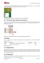
Internal or external supply
The EVB can be supplied through the host interfaces and voltages generated by internal DC-DC. To
use internal supplies, place jumpers on pins 1-2 and 3-4 of pin header J7 (default configuration).
To use external power sources, remove the jumpers and connect the supplies directly to the
BRD_3V3,
BRD_1V8
, and
GND
pins on J7.
Figure 5: Internal/external supply (J7)


