Ublox EVK-MAYA-W2 Скачать руководство пользователя страница 17


EVK-MAYA-W2 - User guide 

UBX-22011269 - R04 

Board description


Page 17 of 20 

C1 – Public 
 

3.6


Bluetooth audio interface 

For Bluetooth voice applications, MAYA-W2  EVB includes a  MAX9860  16-bit  audio codec that 
connects  to the PCM/I2S interface of the module. It also includes a  3.5  mm audio jack (J16)  for 
connecting  a headset. The MAX9860 codec is driven by 19.2 MHz master clock (MCLK) and is 
completely controlled through software using an I2C interface. The codec responds to the I2C slave 
address 0x20 for all write commands and 0x21 for all read operations. 

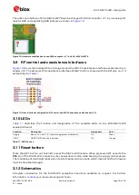
The I2C interface of the audio codec is provided on 

connector J5

, as shown in 

Table 9

. The PCM/I2S 

interface of the MAYA-W2 module is directly connected to the serial audio interface of the MAX9860 
audio codec. The PCM pins are shared with the I2S interface and extend to 

connector J4

, as shown in 

Table 9

. To connect the PCM/I2S interface of MAYA-W2 to the M.2 card connector J2, place jumper 

bridges on J4 positions 1-2, 3-4, 5-6, and 7-8. 

Name 

I/O 

Connector / pin no. 

Description  

I2C_SDA 

I/O 

J5 / 16 

I2C Serial-Data Input/Output 

I2C_SCL 

J5 / 18 

I2C Serial-Data clock 

PCM_CLK 

I/O 

J4 / 2 

PCM clock 
Alternate function: I2S clock 

PCM_SYNC 

I/O 

J4 / 4 

PCM frame sync 
Alternate function: I2S word select 

PCM_DOUT 

J4 / 6 

PCM data out 
Alternate function: I2S data out 

PCM_DIN 

J4 / 8 

PCM data in 
Alternate function: I2S data in 

Table 9: Audio interfaces 

3.7


GPIOs 

Figure 9

 shows the 

pin headers J4 and J5

 that provide direct access to the UART, JTAG, GPIO and 

PCM/I2S interfaces on the MAYA-W2 module. The interface signals are connected through jumpers 
to the M.2 card interface connector J2 or accessed directly through the pin headers. 

3.8


Antenna interfaces 

The evaluation board of EVK-MAYA-W271 includes two standard 50 

 female SMA connectors for 

connecting external antennas or measurement instruments. EVK-MAYA-W276 uses the internal PCB 
antenna of MAYA-W276. 

Table 10

 describes the available radio interfaces of the MAYA-W2 module and the respective antenna 

interfaces on the EVB. 

Product name 

Module antenna interface  Function 

Antenna interface on EVB 

EVK-MAYA-W271 

RF_ANT0 

2.4/5 GHz Wi-Fi 

SMA connector J10 

RF_ANT1 

Bluetooth, shared with IEEE 
802.15.4 on EVK-MAYA-W271 

SMA connector J11 

EVK-MAYA-W276 

Internal PCB antenna 

2.4/5 GHz Wi-Fi,Bluetooth and 
802.15.4 

Table 10: Antenna interface configuration 


Connect the external antennas supplied with EVK-MAYA-W271 to the SMA connectors J10 
and J11.  If 2.4 GHz Wi-Fi and Bluetooth/802.15.4  are used at the same time, bend the 
antennas at a 90° angle to each other or use a coaxial RF cable to increase isolation between 
the antennas. 

Содержание EVK-MAYA-W2

Страница 1: ...com EVK MAYA W2 Evaluation kit for MAYA W2 host based modules User guide Abstract This document describes how to set up the EVK MAYA W2 evaluation kit to evaluate MAYA W2 series multiradio modules wi...

Страница 2: ...al property rights in the products names logos and designs included in this document Copying reproduction or modification of this document or any part thereof is only permitted with the express writte...

Страница 3: ...umpers and connectors 11 3 3 Power supply configuration 12 3 3 1 Internal or external supply 12 3 3 2 VIO configuration 13 3 3 3 Current measurement 13 3 4 Host interface configuration 13 3 5 Host int...

Страница 4: ...W2 allows an external host processor to access several practical features for testing and evaluating the connectivity options supported in MAYA W2 series modules including SD card and M 2 key E adapte...

Страница 5: ...AYA W276 uses the internal PCB antenna on the MAYA W276 module M 2 Key E adapter M 2 Key E adapter to connect to M 2 host sockets Two flat cables are included in the EVK to connect the adapter to ZIF...

Страница 6: ...The driver source code is provided free of charge as open source under NXP licensing terms As open source software the drivers can be integrated or ported to other non NXP based host platforms 1 3 1...

Страница 7: ...e for access to the IEEE 802 15 4 radio host interface Supported operating systems o Linux 3 x 4 x 5 x o Android o FreeRTOS through NXP MCUXpresso 1 5 Operating conditions Table 3 describes the recomm...

Страница 8: ...antenna and an optional SMA connector for connecting an external antenna For more information about the antenna connectors see also Antenna interfaces 2 Connect the host interfaces to the host system...

Страница 9: ...erface on the host system through wires For more information about the SPI interface see also SPI host interface for IEEE 802 15 4 3 Power on the host system The Supply LED D2 on the EVB should turn g...

Страница 10: ...11269 R04 Board description Page 10 of 20 C1 Public 3 Board description 3 1 Block diagram Figure 3 shows a block diagram of the evaluation board with the M 2 and SD card adapters Figure 3 Block diagra...

Страница 11: ...evaluation board and the placement of the connectors and pin headers for jumper configuration Default jumper positions are highlighted in red Figure 4 EVK MAYA W2 connectors and default jumper config...

Страница 12: ...or IEEE 802 15 4 J14 JTAG JTAG connector for MAYA W2 not assembled SW1 Reset button Reset button D2 D3 LEDs Power supply and UART activity indicator LEDs Table 5 MAYA W2 evaluation board connectors 3...

Страница 13: ...th communication SDIO UART mode MAYA W271 and MAYA W276 additionally support an SPI interface for communication with the IEEE 802 15 4 radio SDIO UART SPI mode The MAYA W2 boot mode configuration pins...

Страница 14: ...W2 module through 22 series resistors The SDIO interface can be used for power supply of the EVB The SDIO card adapters support only the SDIO interface which is used for Wi Fi communication of the MA...

Страница 15: ...or M 2 sockets on platforms based on NXP MPUs and MCUs For more information about the Wi Fi Bluetooth M 2 Key E Pinout Definition on NXP host boards see also the NXP AN13049 pin definition 6 Some inte...

Страница 16: ...ce through USB Access is provided through the USB type C connector J1 or the USB lines on the M 2 card interface The USB type C connector can be used for the EVB power supply The routing and selection...

Страница 17: ...nate function I2S word select PCM_DOUT O J4 6 PCM data out Alternate function I2S data out PCM_DIN I J4 8 PCM data in Alternate function I2S data in Table 9 Audio interfaces 3 7 GPIOs Figure 9 shows t...

Страница 18: ...and WCI 2 coexistence interfaces J12 3 10 LEDs Table 11 describes the function and designation of the available LEDs on the EVK MAYA W2 evaluation board Function Description Designator Color Supply B...

Страница 19: ...lution MAC Medium access control MIMO Multiple input multiple output MMC Multimedia card PC Personal computer PCI Peripheral component interconnect PCIe Peripheral component interconnect express PCM P...

Страница 20: ...lox com Revision history Revision Date Name Comments R01 06 May 2022 mzes Initial release R02 22 Jun 2022 lfar Included EVK MAYA W276 and removed EVK MAYA W261 W266 in Document information Updated con...

Отзывы: