


UBX-21008123 - R02
Interfaces and peripherals
Page 29 of 42
C1-Public
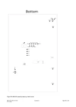
Figure 16 shows the layout of the Raspberry Pi interface described in Table 13. Three mounting holes
can be used for increasing the mechanical stability. The two holes on each side of connector J14 are
common to all Raspberry Pi boards, but the third one is only compatible with the Pi Zero boards.
Figure 16: Pin header J14 that is compatible with the Raspberry Pi GPIO connectors
Conn.
Pin
No.
Raspberry
Pi pin
Description
Schematic
net name
nRF52
pin
Alternate functions and notes
J14
1
3.3 V
3.3 V supply pin
3V3_PI
-
Not connected by default, see also
Powering options
.
2
5 V
5 V supply pin
5V
-
Cannot be used as supply input. Supplied
by USB VBUS and protected from back
powering.
3
GPIO02
Digital I/O
IO_14
P0.11
4
5 V
5 V supply pin
5V
-
Cannot be used as supply input. Supplied
by USB VBUS and protected from back
powering.
5
GPIO03
Digital I/O
IO_15
P0.12
6
GND
Ground
GND
GND
7
GPIO04
Digital I/O
-
-
N/C
J14
MOUNTING HOLES
3V3_PI
IO_14
IO_15
N/C
GND
N/C
IO_13
IO_17
3V3_PI
IO_34
IO_22
IO_26
GND
IO_47
IO_31
IO_33
UART_RTS/IO_36
UART_CTS/IO_37
IO_39
GND
5 V
5 V
GND
RASP_TXD
RASP_RXD
RESET_N
GND
IO_16
IO_18
GND
IO_23
IO_49
IO_50
IO_51
GND
IO_32
GND
IO_52
IO_10
IO_48
J14
2
1
39 40
R57
R58
R59
R60
UART RESISTORS
Raspberry Pi Interface
Содержание EVK-ANNA-B4
Страница 34: ...UBX 21008123 R02 Appendix Page 34 of 42 C1 Public Appendix A Schematics...
Страница 37: ...UBX 21008123 R02 Appendix Page 37 of 42 C1 Public Pages 2 and 6 of the schematic are intentionally omitted...
Страница 39: ...UBX 21008123 R02 Appendix Page 39 of 42 C1 Public Figure 23 ANNA B4 assembly drawing bottom view...