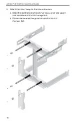
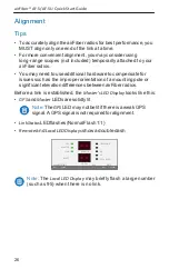
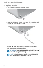
Ubiquiti airFiber 5 Скачать руководство пользователя страница 31

29


Alignment


6. 

Slave 

Aim the 

Slave 

at the 

Master 

to achieve the strongest 

signal level on the 

Remote LED Display 

of the 

Slave

.


Note: 

Values on the 

LED Displays 

are displayed in


negative (-) dBm. For example, 67 represents a received 
signal level of -67 dBm. Smaller numerical values indicate 
stronger received signal levels. For example, a reading of 
49 is stronger than a reading of 55.


Note: 

Maximum signal strength can best be achieved 

by iteratively sweeping through both azimuth and 
elevation.


7. 

Master 

Aim the 

Master 

at the Slave to achieve the strongest 

signal level on the 

Remote LED Display 

of the 

Master

.


Note: 

If the Overload LED lights up, refer to the 

airFiber AF-5/AF-5U User Guide at: 

documentation.ubnt.com/airfiber


8.  Repeat steps 6 and 7 until you achieve a symmetric link, with 

the signal levels within 1 dB of each other. This ensures the 
best possible data rate between the airFiber radios.


9.  Lock the alignment on both airFiber radios by tightening the 

nuts and bolts.


10. Observe the 

Local 

and 

Remote LED Displays 

of each airFiber 

radio to ensure that the values remains constant while 
tightening the nuts and bolts. If any LED value changes during 
the locking process, loosen the nuts and bolts, finalize the 
alignment of each airFiber radio again, and retighten the nuts 
and bolts.


11. For each airFiber radio, close the port cover and ensure that the 

Ethernet cable stays in the cable feed slot.


GPS


MASTER 

LINK


OVERLOAD


REMOTE


RESET


8X


6X


4X to 0.25X


MANAGEMENT


ACT             SPEED


LOCAL


AUX 

DATA


ACT             SPEED


Содержание airFiber 5

Страница 1: ...5 GHz Point to Point 1 0 Gbps Radio Model AF 5 AF 5U...

Страница 2: ......

Страница 3: ...more information Package Contents airFiber AF 5 AF 5U I Bracket Upper Mount Bracket with Elevation Rod Lower Mount Bracket Pole Clamps Qty 2 M10x150 Carriage Bolts Qty 4 M10x100 Carriage Bolts Qty 2 S...

Страница 4: ...F 5 AF 5U Quick Start Guide Hardware Overview Side Lanyard Attachment Loop Elevation Rod Hex Nut to adjust Elevation Rod Pre Installed M10 x25 Flanged Bolts Grounding Point Lanyard Attachment Loop Ass...

Страница 5: ...of the remote airFiber radio Local Display Displays the received signal strength in dBm of thelocalairFiberradio Management Port 10 100 Mbps secured port for configuration By default this is the only...

Страница 6: ...perational Weak Signal Master Off Slave mode On Master mode Link Off RF Off Short Flash Syncing Normal Flash Beaconing Long Flash Registering On Operational Remote On Displays the received signal stre...

Страница 7: ...lash QPSK MIMO Normal Flash 1x QPSK xRT Short Flash x QPSK xRT Port LEDs Short Flash 1 3 on off cycle NormalFlash 1 1on offcycle LongFlash 3 1on offcycle xtreme Range Technology LED State Status Manag...

Страница 8: ...the highest point on the structure For tower installations at least 3 m below the top of the tower Ground wires min 10 AWG 5 mm2 and max length 1 m As a safety precaution ground the airFiber radios t...

Страница 9: ...er and the Management port Configure the device settings in the airFiber Configuration Interface Once configuration is complete disconnect the cables to move theairFiberradios Pre assemblethemountingh...

Страница 10: ...thernet cable from the Data port to the Ethernet port labeled POE on the GigE PoE Adapter 4 Connect the Power Cord to the power port on the GigE PoE Adapter Connect the other end of the Power Cord to...

Страница 11: ...provides more frequency planning options at the cost of higher latency and throughput Full duplex operation provides thehighest throughput and lowest latency however you have fewer frequency manageme...

Страница 12: ...b browser Type http 192 168 1 20 in the addressfieldandpressenter PC orreturn Mac 4 The login screen will appear Enter ubnt in the Username and Password fields Select your Country and Language You mus...

Страница 13: ...uration 7 Click the Wirelesstab 8 Enter the Basic Wireless Settings a ForoneairFiberradio selectMasterastheWirelessMode For the other airFiber radio keep the default Slave b Enter a name in the Link N...

Страница 14: ...agement is enabled by default so each airFiber radio must have a unique IPAddress If the airFiber radios use thesameIPAddress youmayloseaccesstotheairFiberradios via the Data ports Click the Network t...

Страница 15: ...mounting hardware of the airFiber radio can be pre assembled before pole mounting Mounting Hardware Pre Assembly 1 Insert two M10x150 Carriage Bolts into the Lower MountBracket 2 InserttwoM10x150Carri...

Страница 16: ...airFiber AF 5 AF 5U Quick Start Guide 3 Attach the Lower Mount Bracket to the I Bracket using two SerratedFlange Bolts Ensure that the slots face up and securely tighten the bolts Proper slot orientat...

Страница 17: ...AttachtheUpperMountBracketwithElevationRodtothe I Bracket using two Serrated Flange Bolts Note Ensure that the orientation of the Upper Mount Bracket matches the illustration below with the Elevation...

Страница 18: ...Quick Start Guide 5 Attach the Pole Clamps to the Mount Brackets a Slide the slotted hole of each Pole Clamp over one upper and one lower M10x150 Carriage Bolt b Place one Serrated Flange Nut on each...

Страница 19: ...SupportBracketthathastwoslottedholes b SlidetheslottedholeoftheotherAzimuthSupportBracket over one M10x100 Carriage Bolt c Place one Serrated Flange Nut on each M10x100 Carriage Bolt 7 Check the four...

Страница 20: ...radio will be attached Note The mounting assembly can accommodate a 38 1 101 6mm 1 5 4 0 pole a OrienttheAzimuthSupportBracketsaroundthepolesoitis aimedinthedirectionoftheotherairFiberradio b Slide t...

Страница 21: ...mounting assembly around the pole so it is aimed in the direction of the other airFiber radio b Slide the open slot of each Pole Clamp over the corresponding M10x150 CarriageBolt c Tighten the Serrate...

Страница 22: ...airFiber AF 5 AF 5U Quick Start Guide 20 3 Lift the airFiber radio and align the two lower Pre Installed M10x25 Flanged Bolts with the slots on the Lower Mount Bracket Seat the bolts in the slots...

Страница 23: ...rdwareInstallation 21 4 Align the two upper Pre Installed M10x25 Flanged Bolts of the airFiber radio next to the slots on the Upper Mount Bracket Lift the airFiber radio and seat the bolts in the slot...

Страница 24: ...wire min 8 AWG or 10 mm2 to the lug and replace the nut to secure the wire c Securetheotherendofthegroundwiretoagrounded mast pole tower or grounding bar WARNING FailuretoproperlygroundyourairFiber u...

Страница 25: ...eedanoutdoor shieldedCAT6cableupthroughthe rightmostcablefeed slotonthe bottomoftheportcover b Connect the cable to theData port c Create a strain relief for the Ethernet cable by feeding a Cable Tie...

Страница 26: ...rt labeled LAN on the GigE PoE Adapter 5 Connect the Power Cord to the power port on the GigE PoE Adapter Connect the other end of the Power Cord to a power source Note For added protection we recomme...

Страница 27: ...a finished installation with recommended surgeprotectorsinstalled Ground to Pole Tower or Grounding Block Max 1 m from Ground Bonding Point Outdoor GigE PoE Surge Protector Outdoor GigE PoE Surge Prot...

Страница 28: ...roper orientation of a mounting pole or significantelevationdifferencesbetweenairFiberradios Before a link is established the Master s LED Display looks like this GPS and Master LEDs are solidly lit N...

Страница 29: ...ransmissionsfromtheMaster 1 Ensurethatthefollowingboltsandnutsareloose Four Pre Installed M10x25 Flanged Bolts on the airFiber radio two on each side Four M10 Hex Nuts used to lock the elevation align...

Страница 30: ...Master and Slave 4 Slave Visually aim the Slave at the Master Toadjust the Slave s position a Rotate the airFiber radio on the pole to align the azimuth b Use the hex nut on the Elevation Rod to adju...

Страница 31: ...rFiber AF 5 AF 5U User Guide at documentation ubnt com airfiber 8 Repeat steps 6 and 7 until you achieve a symmetric link with the signal levels within 1 dB of each other This ensures the best possibl...

Страница 32: ...F 5 AF 5UUserGuideforinstructionsonthe airFiber Configuration Interface and audio tone methods Installer Compliance Responsibility Devices must be professionally installed and it is the professional i...

Страница 33: ...ti Networks Inc All rights reserved Ubiquiti Ubiquiti Networks the UbiquitiUlogo theUbiquitibeamlogo airFiber TOUGHCable andxRTaretrademarks or registered trademarks of Ubiquiti Networks Inc in the Un...

Отзывы: