UAV-1000xxx-001
ECCN 7A994
Page
1 | 32
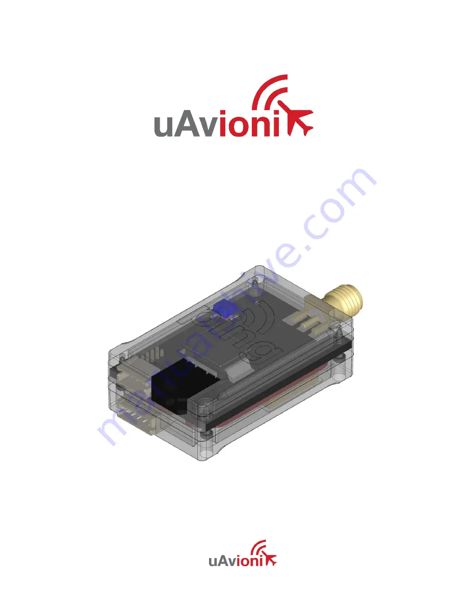
Ping20S
User and Installation Guide
Страница 1: ...UAV 1000xxx 001 ECCN 7A994 Page 1 32 Ping20S User and Installation Guide ...
Страница 2: ...in any storage medium for any purpose without the express written permission of uAvionix uAvionix grants permissions to download a single copy of this guide onto an electronic storage medium to be viewed for personal use provided that the complete text of this copyright notice is retained Unauthorized commercial distribution of this manual or any revision hereto is strictly prohibited uAvionix is ...
Страница 3: ...UAV 1000xxx 001 ECCN 7A994 Page 3 32 1 Revision History Revision Date Comments A 12 19 16 Initial release B 5 25 17 Export Control ...
Страница 4: ... Security BIS as Export Control Classification Number ECCN 7A994 These items are controlled by the U S Government and authorized for export only to the country of ultimate destination for use by the ultimate consignee or end user s herein identified They may not be resold transferred or otherwise disposed of to any other country or to any person other than the authorized ultimate consignee or end ...
Страница 5: ...esponsible for any transportation cost This warranty does not apply to cosmetic damage consumable parts damage caused by accident abuse misuse water fire or flood damage caused by unauthorized servicing or product that has been modified or altered IN NO EVENT SHALL UAVIONIX BE LIABLE FOR ANY INCIDENTAL SPECIAL INDIRECT OR CONSEQUENTIAL DAMAGES WHETHER RESULTING FROM THE USE MISUSE OR INABILITY TO ...
Страница 6: ...al Specifications 12 6 1 Markings 13 7 Equipment Limitations 13 7 1 Installation 13 7 1 1 Modifications and Use Outside of Intended Scope 13 7 1 2 Deviations 13 7 1 3 Configurable Options 13 7 1 4 Approvals 13 8 Equipment Installation 15 8 1 Unpacking and Inspecting 15 8 2 Mounting 15 8 3 Connections 16 8 4 Wiring Diagram 17 Mating Connector Molex 0436450200 18 8 5 Cooling Requirements 19 8 6 Wiri...
Страница 7: ...nna Cable 22 9 Configuration 24 9 1 ICAO Number 24 9 2 VFR Squawk Code 24 9 3 Callsign 24 9 4 Aircraft Maximum Speed 24 9 5 Aircraft Category 25 9 6 ADS B RX Capability 25 9 7 Programming 26 10 Post Installation Checks 27 11 Continued Airworthiness 27 12 Environmental Qualification Forms 28 ...
Страница 8: ...ns from both ground radar and airborne collision avoidance systems In all cases the interrogations are received by the transponder on 1030MHz and replies are transmitted on 1090MHz This system will enable the aircraft to be visible to ATC and other aircraft equipped with Traffic Advisory System TAS as defined in TSO C174 Traffic Alert and Collision Avoidance System I TCAS I as defined in TSO C188 ...
Страница 9: ...Code Call sign Squawk Code IDENT Transponder Mode GDL 90 Compatible Control Protocol See Appendix A COM1 TX 57600bps Heartbeat Ownship Geometric Altitude GDL 90 See Appendix B FYXnav Interface Interface Specification Protocol FYXnav COM 2 115200bps GPS Altitude Encoder ICAO number VFR Squawk Code Callsign Aircraft Maximum Speed Aircraft Category Aircraft Vso Aircraft Length and Width GPS Antenna O...
Страница 10: ...ay the TABS aircraft TABS are intended to be used on aircraft that are exempt from carrying a transponder or ADS B equipment such as gliders balloons and aircraft without electrical systems A TABS will allow these exempted aircraft to be visible to other aircraft equipped with Traffic Advisory System TAS as defined in TSO C147 Traffic Alert and Collision Avoidance System I TCAS I as defined in TSO...
Страница 11: ...rborne Electronic Hardware UAV 1000xxx 001 A 1 5 5 Supplied Accessories Part Part Number Revision Ping20S UAV 1000xxx 001 A Power Adapter Battery Cable A FYXnav TSO GPS Baro UAV 1000568 001 A Ping20S FYXnav Cable UAV 1000xxx 001 A Wi Fi Programmer Dipole Antenna UAV 1000653 001 A Ping20S Mounting Tape FYXnav Mounting Tape Ping20S User Manual UAV 1000xxx 001 A ...
Страница 12: ...irements 11 16VDC Typical 2 4W On Alt 0 1W Standby Altitude 35 000ft Operating Temperature 45 C to 70 C Humidity Tested to Category DO 160G Category B2 Transmit Frequency 1090MHz 1MHz Transmit Power 20W nominal 16W minimum at antenna after allowing for 0 5dB connector losses and 1 5dB cable losses Transmitter Modulation 6M75 V1D Receiver Frequency 1030MHz Receiver Sensitivity 74dBm 3dB Weight 15gr...
Страница 13: ...ed scope or use the device with any antenna other than the one shipped with the device 7 1 2 Deviations There are no deviations from the MPS of TSO C199 Class A Device apart from output power 7 1 3 Configurable Options Accessing or altering configurable options not intended to be operated may cause pilot distraction 7 1 4 Approvals Approvals do not cover adaptations to the aircraft necessary to ac...
Страница 14: ...nd quality control standards required by a technical standard order TSO Installation of this device requires separate approval This device does not meet requirements for use in transponder rule airspace as defined in 14 CFR 91 215 and ADS B rule airspace as defined in 14 CFR 91 225 ...
Страница 15: ...ner and all packing materials 8 2 Mounting The Ping20S is designed to be mounted in any convenient location in the cockpit the cabin or an avionics bay The following installation procedure should be followed remembering to allow adequate space for installation of cables and connectors Select a position in the aircraft that is not too close to any high external heat source The Ping20S is not a sign...
Страница 16: ... 001 ECCN 7A994 Page 16 32 8 3 Connections Whenever power is supplied to the transponder a 50ohm load must be provided to the SMA connection You can use the supplied antenna or a commercially available 50ohm load ...
Страница 17: ...UAV 1000xxx 001 ECCN 7A994 Page 17 32 8 4 Wiring Diagram ...
Страница 18: ...7600bps Control 2 TX Out 3 3V Serial 57600bps GDL 90 3 Power 5V Out 4 Ground Mating Connector JST ZHR 4 Pins SZH 002T P0 5 FYXnav Interface Pin Type Physical Rate Link 1 NC 2 RX In 3 3V Serial 115200bps MavLink 3 TX Out 3 3V Serial 115200bps GDL 90 4 Power 5V Out 5 Ground Mating Connector JST ZHR 5 Pins SZH 002T P0 5 LEDs LED SOLID FLASHING RED FAULT Reply Transmit GREEN Powered Receiving Interrog...
Страница 19: ...reak through on adjacent audio wiring if it is not possible to route them separately The distance between the Ping20S and the power source is limited by the impedance of the wire between them The Ping20S is powered directly from aircraft power and therefore the acceptable voltage drop in the power line is what limits the distance The Ping20S needs an impedance of less than 0 5ohm in the power line...
Страница 20: ...d propeller s It should also be well removed from landing gear doors access doors or other openings which will break the ground plane for the antenna The antenna should be mounted in a vertical position when the aircraft is in level flight Avoid mounting the antenna within 1 meter of the ADF sense antenna or any COMM antenna and 2 meters from the transponder to the DME antenna Where practical plan...
Страница 21: ...energy is radiated inside the aircraft When a conventional aircraft monopole antenna is used it relies on a ground plane for correct behavior For ideal performance the ground plane should be large relative to the wavelength of the transmission which is 275mm In a metal skinned aircraft this is usually easily accomplish but is more difficult in a composite or fabric skinned aircraft In these cases ...
Страница 22: ...cceptable cable has less than 1 5dB loss for the run length needed has a characteristic impedance of 50ohms has double braid screens or has foil and braid screen Once the cable run length is known a cable type with low enough loss per meter that meets the above requirements can be chosen Longer runs require lower loss cable The following table is a guide to the maximum usable lengths of some commo...
Страница 23: ...08801 When routing the cable Route the cable away from sources of heat Route the cable wiring away from potential interference sources such as ignition wiring 400Hz generators fluorescent lighting and electric motors Allow a minimum separation of 300mm from an ADF antenna cable Keep the cable run as short as possible Avoid routing the cable around tight bends Avoid kinking the cable even temporari...
Страница 24: ...a 24 bit number issued to the aircraft by the registration authority of the aircraft These addresses are usually written as a 6 digit hexadecimal number although you may also encounter one written as an 8 digit octal number The FYXnav understands the hexadecimal format An octal number must be converted to hexadecimal format before entering 9 2 VFR Squawk Code VFR squawk Mode 3 A code is a pre prog...
Страница 25: ... threats and to plan avoiding action by the TCAS equipped aircraft The airspeeds are grouped in ranges 9 5 Aircraft Category To assist ATC tracking of aircraft an aircraft category can be transmitted 9 6 ADS B RX Capability The ADS B transmissions include an indication to the ground stations of whether the aircraft includes a 1090MHz ADS B receiver a UAT ADS B receiver or both ...
Страница 26: ... via the supplied Wi Fi adapter and mobile device application Please refer to the following documentation FYXnav datasheet http uavionix com downloads fyxnav docs uavionix fyxnav data sheet pdf FYXnav quick start guide http uavionix com downloads fyxnav docs uavionix fyxnav quick start guide pdf Ping App iOS quick start guide http uavionix com downloads pingapp uavionix ping app quick start guide ...
Страница 27: ...s requirement is also generally due to antenna or wiring issues Verification of the GPS position source and ADS B outputs Whenever a valid position is received by the transponder and the transponder is in any mode other than standby ADS B Extended Squitter messages should be observed on the transponder test set 11 Continued Airworthiness Other than for periodic functional checks required by the re...
Страница 28: ...ircraft zone 2 type 3 4 5 to Category S level M type 1 Helicopters to Category U level G Explosion 9 0 Equipment identified as Category X no test Waterproofness 10 0 Equipment identified as Category X no test Fluids Susceptibility 11 0 Equipment identified as Category X no test Sand and Dust 12 0 Equipment identified as Category X no test Fungus 13 0 Equipment identified as Category X no test Salt...
Страница 29: ...return character A1 Physical Interface The Control interface uses RS 232 signaling levels The port is configured for the following characteristics Baud Rate 57600 baud Start Bits 1 Data Length 8 Stop Bits 1 Parity None Flow Control None A2 Control Messages The following table summarizes the Control messages that the Ping20S receives Msg ID Description Notes Ref CS Call Sign 1 min interval or on ch...
Страница 30: ...ute or when a change occurs Message Length 15 bytes Byte Contents Description 1 ASCII 0x5E 2 C ASCII C 0x43 3 S ASCII S 0x53 4 ASCII space 0x20 5 12 dddddddd ASCII Flight ID all 8 characters are mandatory right pad with space 13 14 dd Checksum of bytes 1 through 12 In hex ASCII i e FA 15 r ASCII carriage return 0x0D Example CS UAVIONIX87 r ...
Страница 31: ...dddd ASCII squawk code 13 e See emergency field table below 14 h Health bit in hex ASCII 1 15 16 dd Checksum of bytes 1 through 14 In hex ASCII i e FA 17 r ASCII carriage return 0x0D Mode Field m Definition ASCII O OFF 0x4F A STBY 0x41 C ON 0x43 S ALT 0x53 Ident Field i Definition ASCII I Ident Enabled 0x49 Ident is Inactive 0x2D Emergency Field e Definition ASCII 0 None 0x00 1 General 0x01 2 Medi...
Страница 32: ...Data Interface Specification can be found at https www faa gov nextgen programs adsb wsa media GDL90_Public_ICD_RevA PDF Ping20S transmits the following messages Msg ID Description Notes Ref 010 Heartbeat 1 second interval 3 1 1010 Ownship Report 1 second interval 3 4 1110 Ownship Geometric Report 1 second interval 3 8 ...
Страница 33: ...ions from the Minimum Performance Standards of DO 181E and DO 260B at 20W nominal output power Features Technical Specifications Mode S 1030MHz transponder Transmits ADS B on 1090MHz Extended Squitter Meets MOPS DO 181E 20W Meets MOPS DO 260B 20W TSO C199 Class A device 20W SMA Antenna Connector US Patents Pending Regulatory FCC 47CFR part 87 Meets the performance requirements of TSO C199 integrat...
Страница 34: ... ECCN 7A994 Electrical Specification Power Interface Pin Type 1 Power 11 16V 2 Ground Mating Connector Molex 0436450200 Pins 0462350001 Data Interface Pin Type 1 Input RXD SDA CONTROL 2 Output TXD SCL GDL 90 3 Power 5V 4 Ground Mating Connector JST ZHR 4 Pins SZH 002T P0 5 Navigation Source Interface Pin Type 1 Input UTC 2 Input RXD MavLink 3 Output TXD GDL 90 4 Power 5V 5 Ground Ground Mating Con...
Страница 35: ...Logo font Helvetica Neue LT Std 75 Bold uAvionix Brand Logo Specs REV D 20160329 PANTONE P 48 16 C OR EQUIVALENT PANTONE P 179 11 C OR EQUIVALENT uAvionix Ping20S Transponder QUICK START GUIDE ...
Страница 36: ...nstall the uAvionix Ping App from the Apple App Store or Google Play Search for uAvionix Ping Installer or use the QR codes below Install Connect the ping programmer to FYXnav using the provided JST ZHR 5 cable Connect ping programmer to a power source using a Micro USB cable ...
Страница 37: ...onix as the WPA password for the secure Wi Fi network then tap Join Note No Internet Connection message is normal After device is connected proceed to step 3 2 Join Join your mobile device to the wireless network named Ping XXXX using the procedure for your device The WPA passphrase is uavionix The process for iOS is shown below ...
Страница 38: ...ould be set to your aircraft type UAV is the selection for unmanned vehicles VFR Code Enter the default VFR code for your country The United States code is 1200 Maximum aircraft speed Select your aircraft maximum speed ADS B In Capability Select aircraft ADS B receive capability If you do not have a separate ADS B receiver this should be set to None Aircraft Length Width Select the length width va...
Страница 39: ...tor Verify all fields are correct for your aircraft The monitor fields will only populate when FYXNav has a GPS fix A GPS fix is indicated by a flashing red LED A fix is not necessary for programming but is required to monitor the current configuration Disconnect power from ping programmer Disconnect FYXnav from ping programmer ...
Страница 40: ...he sky Mount FYXnav using the provided double sided adhesive Remove both top and bottom backing from provided double sided tape Adhere double sided tape to the underside of FYXnav in the correct orientation so the barometer and 5 pin connector are not blocked by the adhesive Mount ping20S to a suitable flat surface using the provided double sided mounting tape Affix mounting tape to ping20S and at...
Страница 41: ...rcraft power source For additional support uavionix com support 6 Connect Connect remaining 5 pin connector from FYXNav to ping20S Mount and connect the transponder antenna to ping20S using supplied cable The antenna should be mounted in a vertical orientation ...