


Part # 4518632 (02/19/08)
Page 6
Before connecting new pipe to your US Range Fryer, the
pipe must be thoroughly blown out to depose of all foreign
particles. If these foreign particles get into the burner and
controls they will cause improper and sometimes dangerous
operation.
When using thread compound, use it sparingly and one on
male threads. Use compound that is impervious to the action
of Propane gases. Do not put any on the first two threads.
This will prevent fouling the controls and clogging the pilot
and main burner orifices.
Make sure that installer checks all plumbing with a soap
solution for leaks. DO NOT USE A FLAME, MATCHES,
CANDLES, or other ignition source in checking for leaks.
Frypot
Before leaving the factory, the fryer was tested, and the
thermostat was calibrated, with oil in the frypot; therefore,
it is necessary to clean the frypot before adding frying
compound. Rinse the frypot with clean water, then put some
fryer cleaner on a damp cloth, full strength, and wipe the
entire frypot clean. Rinse it thoroughly and wipe dry. The
fryer is now ready for use. If the fryer doe not have a stainless
steel frypot and is not to be used immediately after cleaning,
coat the entire frypot surface with shortening or cooking oil
to prevent rust.
Casters
A. The installation shall be made with a connector that
complies with the Standard for Connectors for Moveable
Gas Appliances, ANSI Z21.69/CSA 6.16, Addenda Z21.69B-
2006/CSA 6.16B-2006 (or latest edition), and a quick-
disconnect device that complies with the Standard for
Quick Disconnects for Use with Gas Fuel, ANSI Z21.41/
CSA 6.9, Addenda Z21.41A-2005/CSA 6.16A-2005 (or
latest edition).
B. The front casters of the unit are equipped with brakes
to limit the movement of the fryer without depending
on the connector and any quick disconnect device or its
associated piping to limit the appliance movement.
C. Please be aware, required restraint is attached to a
bracket on the fryer (connection point is located on the
left rear caster of the fryer), and if disconnection of the
restraint is necessary, be sure to reconnect the restraint
after the fryer has been returned to its originally installed
position.
NOTE: When installed, the fryer must be restrained to
prevent tipping in order to avoid the splashing of hot liquid.
The means of restraint may be the manner of installation,
such as connection to a battery of appliances. Or installing
the fryer in an alcove, or by separate means, such as
adequate ties.
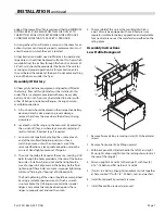
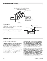
Legs
Raise front of the unit and block. Do not lay unit on its back.
Position leg insert into leg retainer opening and tap up until
it seats at collar flange. Repeat at rear of unit making sure all
four legs are adjusted to same height. Legs can be adjusted
to overcome an uneven floor.
CAUTION:
These types of US Range Fryers cannot be
installed on a masonry base or without proper clearance
from floor. Primary air is supplied to the ‘jet – type” burner
from the front and mainly from the bottom of the fryer. If
installed on a masonry base or directly on floor without the
use of the factory supplied 6" (152mm) legs or casters, a
louvered door option is required.
Ventilation and Air Supply
One of the most important considerations is ventilation.
The fryer must be installed so that products of combustions
are removed efficiently, but so that the kitchen ventilation
system does not produce drafts that interfere with proper
burner operation. The fryer flue opening must
NOT
be placed
close to the intake of the exhaust fan.
The fryer must never have its flue extended in a chimney
fashion. This changes the combustion characteristics of the
fryer. This will cause the fryer to be slow to recover, frequently
cause delayed ignition, and sometimes cause pilot outage.
The ideal method of ventilating a fryer is the use of a
properly designed canopy which should extend six inches
(6”) (152mm) beyond all sides of the appliance and six feet
(6’) (1289mm) from the floor.
Many operators do not realize that the finest ventilation
system will break down when it is not maintained properly.
The duct system, the hood, and the filter bank must be
cleaned on a regular basis and kept free of grease.
Adequate distances must be maintained from the flue outlet
of the fryer to the lower edge of the filter bank. Filters should
never be installed in the horizontal position. They should be
installed at an angle of 45 degrees, and a drip tray should be
located beneath the lowest edge of the filter. NFPA Standard
No.96 states that “A Minimum distance of 18” (457mm)
should be maintained between the flue outlet and the lower
INSTALLATION
continued


