background image

0813 IH-1675

PAGE 4 OF 11

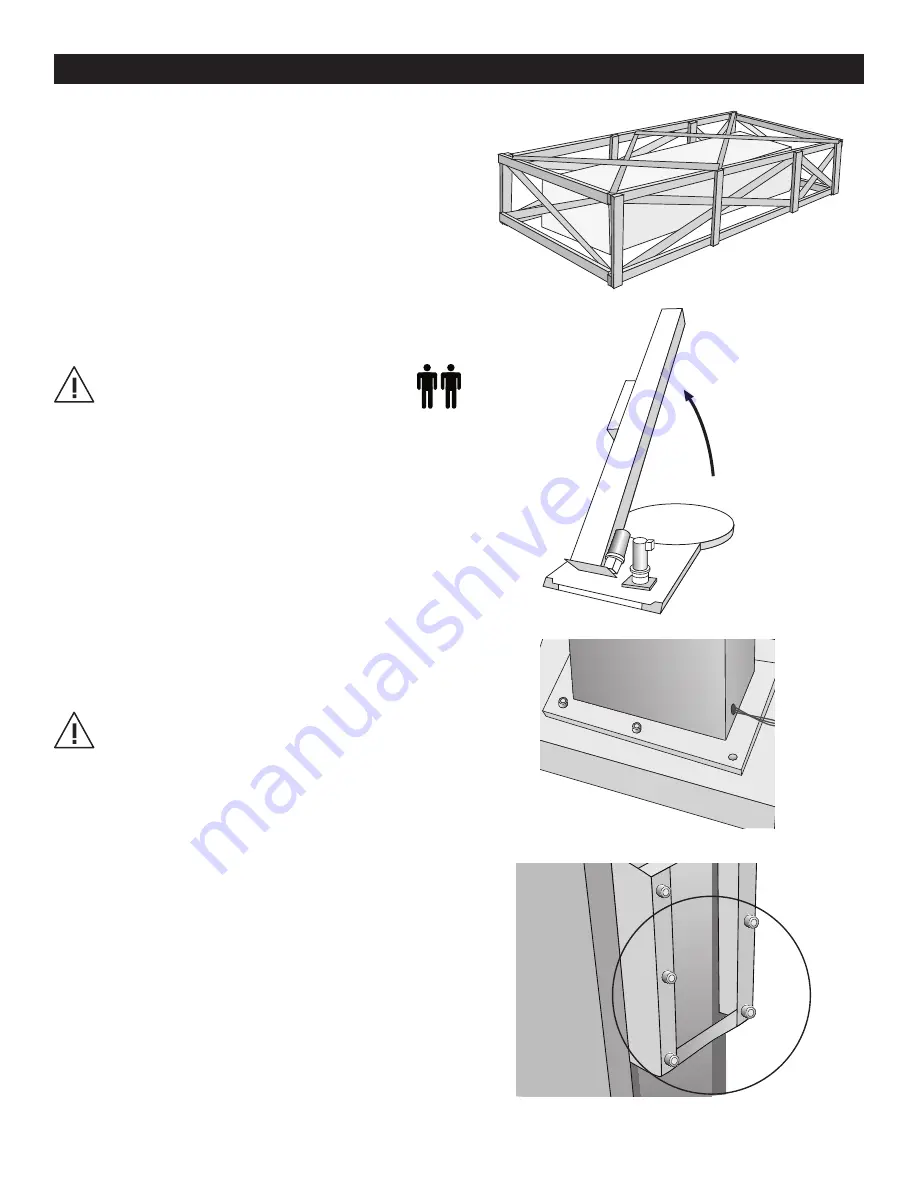
1.  The H-1675 will arrive with similar crating to what is shown 

to the right. Please remove the protective packaging and 

prepare the unit to stand up. (See Figure 2) 


2.  Once the machine has been successfully uncrated, the 

next step is to begin erecting the tower. Start by leaning 

the tower until fully upright. (See Figure 3)

caUTion: Heavy materials! Two or more 

people are required for assembly. 


3.  Align the 5 bolts in the threaded inserts and tighten 

completely. Next, the carriage will need to be 

mounted to the tower. (See Figure 4)

caUTion: always have one or more people 
supporting the tower while tightening bolts. 


4.  To mount the carriage, start by removing the bottom  

4 bolts from the carriage mount bracket. (See Figure 5)

aSSembLY inSTRUcTionS

Figure 2

Figure 3

Figure 4

Figure 5

Содержание H-1675

Страница 1: ... 20 Roll Width Capacity CAUTION Motor control equipment and electronic controllers are connected to hazardous line voltages When servicing drive and controllers there may be exposed components with housings or protrusions at or above line potential Extreme care should be taken to protect against shock The user is responsible for conforming to all applicable code requirements with respect to ground...

Страница 2: ...0813 IH 1675 PAGE 2 OF 11 SYSTem description Motor Box Film Carriage Stretch Handle Tower Control Box Tension Adjustment Knob Foot Safety Bar Seat Turntable ...

Страница 3: ...rea add the weight of the trucks to the weight bearing stress tolerance requirements MACHINE SET UP 1 Place skidded machine close to the designated wrap area Remove all shipping fasteners holding the machine to the pallet The machine may be crated with the tower tilted down with the motor cover front carriage roller removed for shipping purpose 2 Place forks of the forklift through the tubes provi...

Страница 4: ...ing the tower until fully upright See Figure 3 CAUTION Heavy Materials Two or more people are required for assembly 3 Align the 5 bolts in the threaded inserts and tighten completely Next the carriage will need to be mounted to the tower See Figure 4 CAUTION Always have one or more people supporting the tower while tightening bolts 4 To mount the carriage start by removing the bottom 4 bolts from ...

Страница 5: ...e Figure 6 6 Align the top two bolts with slotted bolt holes at the top of the carriage and hang in place See Figure 7 7 The next step is to remount the photo sensor from its protected shipping position See Figure 8 8 Tighten up all 6 bolts on the back of the carriage See Figure 9 Figure 6 Figure 7 Figure 8 Figure 9 ...

Страница 6: ...0813 IH 1675 PAGE 6 OF 11 CONTROL BOX TURNTABLE SPEED CARRIAGE SPEED START BANDING BOTTOM WRAPS TOP WRAPS TURNTABLE JOG WRAP MODES SYSTEM RESET CARRAIGE JOG INFO ...

Страница 7: ... you to manually operate the turntable When this button is pushed the light on the button s upper left is on Push START button to run the table Pushing the button again will stop the turntable and the light will turn off This button may be used in conjunction with the CARRIAGE JOG button The CARRIAGE JOG button allows you to manually operate the carriage When this button is pushed one of the light...

Страница 8: ...r reinforcing wraps in automatic or manual mode Push and hold this button the carriage will stop raising lowering When released the carriage will resume its movement The EMERGENCY STOP button stops the turntable in the event of emergency This will NOT stop the turntable instantly The turntable will coast to a stop depending on the load s weight after this button is pushed This switches the main po...

Страница 9: ...e film as instructed and attach it to the product 4 Set the desired numbers for top and bottom wrap counts 5 Select wrapping mode A or B 6 Press the START button to initiate cycle Stop condition 1 In the event of an emergency press the STOP button This cancels the current wrapping cycle and immediately stops the system The turntable will coast to a stop 2 Correct the problem 3 Pull the STOP button...

Страница 10: ...tons turn the main disconnect switch ON 4 Release the buttons after the screen shows EE 5 Push the START button The machine will run the test which takes approximately 2 minutes 6 The screen will display the alarm code Refer to the table below for code information A1 F1 E1 G1 B1 C1 D1 B2 A2 C2 DISPLAY POSSIBLE PROBLEM LOCATION S A1 Film carriage Safety Bar EMERGENCY STOP button Electrical enclosur...

Страница 11: ...om Film Carriage foot Film carriage malfunctioning FILM CARRIAGE SPEED dial not set high enough Adjust potentiometer towards 100 to set speed Resistance of potentiometer not equal to 5K_ across Tighten wiring replace dial if necessary The carriage limit switch lever arm is obstructed Remove obstruction and or clean limit switch head Microcontroller card inside electrical enclosure not turned on Ch...

Отзывы: