

12
CO29, CO75
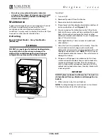
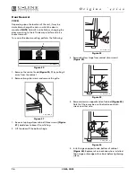
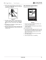
Figure 13
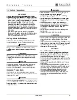
6. Place the two hook-hinges
(Figure 13, 1)
located on
the rear bottom side of the grille onto the front lip of
the unit base. Tilt the grille up into position and align
the grille mounting hole with the grille screw hole on
the cabinet.
7. Insert the screw
(Figure 11, 2)
. Do not overtighten.
8. Reinstall the control knob
(Figure 11, 1)
.
9. Reconnect power to the unit.
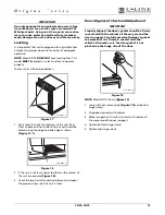
Ice Maker Maintenance
Inlet Screen
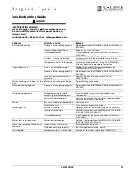
Interval - Every Twelve Months
The solenoid valve inlet screen must be cleaned at least
once each year as follows:
1. Shut off the water at the main supply valve.
2. Pull the unit out to access the back panel.
3. Disconnect electrical power to the unit.
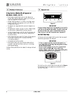
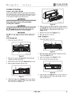
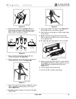
Figure 14
4. Disconnect the hose connector
(Figure 14, 1)
from the
water solenoid valve
(Figure 14, 2)
.
5. DO NOT remove the inlet screen from the water
solenoid valve. Use a tooth brush to gently clean any
sediment from the inlet screen.
6. Re-connect the water supply hose connector
(Figure
14, 1)
to the water solenoid valve
(Figure 14, 2)
.
Tighten the connector securely.
7. Open the water main supply valve and check for
leakage at the water hose connection. Ensure that the
water supply line is not kinked.
8. Reconnect power to the unit before re-installing.
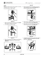
Ice Cube Thickness Adjustment
Interval - As Required
On ice maker equipped models, the cube size may be
adjusted by changing the amount of water injected into
the ice maker assembly as follows:
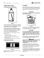
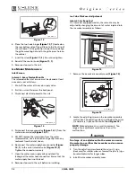
Figure 15
1. Remove the ice maker assembly cover
(Figure 15)
.
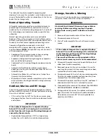
Figure 16
2. Locate the adjusting screw on the ice maker assembly
control box. The adjusting screw is just below the minus
(-) and plus (+) signs on the control box
(Figure 16)
.
NOTE:
Make adjustments in small increments. Too
large of an adjustment could cause the unit to
malfunction.
CAUTION
Too large of an adjustment to the screw can cause
the water to overflow the ice maker and can cause
property damage.
3. Turn the adjusting screw toward the minus (-) sign
(clockwise) for smaller cubes or toward the plus (+) sign
(counterclockwise) for larger cubes.
4. Install the ice maker assembly cover.
ULIN_0154_A
2
1
2
1
ULIN_0054_A
automatic
ICE MAKER
ULIN_0055_A
ULIN_0056_A
ULIN_016357_30089.fm Page 12 Monday, March 27, 2006 10:25 AM
Содержание Combo CO29
Страница 1: ...Use and Care Guide CO29 CO75 Combo Models CO29 CO75...
Страница 4: ...4 CO29 CO75 This page intentionally left blank...
Страница 20: ...20 CO29 CO75 This page intentionally left blank...
Страница 21: ...CO29 CO75 21 This page intentionally left blank...
Страница 22: ...22 CO29 CO75 This page intentionally left blank...


