background image

                                         Dimension BST 1200es / SST 1200es User Guide

  Maintenance  49

Liquefier Tip Replacement

Replace Tips at approximately 2000 hours - depending upon 
operating conditions. Tips can also be damaged by improper care 
while performing maintenance in the area around the tips.

Inspect the heat shield Teflon shield for wear or damage each time 
the liquefier tips are replaced.

NOTE

CatalystEX displays the tip time (hrs) - from the Printer Services Tab - 
Printer Info button (Tip time will reset to zero after replacement).

Removing Tips

1.  Enter 

Tip Maintenance

 - 

Replace Tips

From Idle, Select 

Maintenance

 > 

Machine > Tip


then Replace.

The printer will display 

Load Model - Unloading

followed by 

Tip Maintenance - Adjusting 

Temperature

After the temperature has stabilized, the printer will display 

Tip Maintenance - Replace Tips

. You can now 

open the printer door and replace the tips - or you can 

Cancel

 the tip replacement procedure.

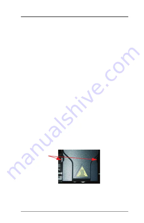
2. Remove Plastic Head Cover

Remove plastic head cover by squeezing raised pads on 
sides of cover. 

Figure 18: Removing the Head Cover

3. Remove Tips 

(

Figure 19 on page 50

)

Squeeze Tabs
(one on each side)
to Remove Cover.

Содержание BST 1200es

Страница 1: ...BST 1200es SST 1200es User Guide...

Страница 2: ...f this equipment in a residential area is likely to cause harmful interference in which case the user will be required to correct the interference at his own expense Changes or modifications to the Di...

Страница 3: ...deling quickly The system models with ABS plastic so modeled parts are strong and durable ABS also ensures you ll be able to drill tap sand and paint your creations With the speed and convenience of B...

Страница 4: ...does not indicate a procedure that can cause injury or damage if it is not followed A NOTE will follow the paragraph of instruction to which it relates The Dimension printer guides you through operati...

Страница 5: ...lding Parts Removing Completed Parts and Removing Support Material The tasks presented are common procedures accomplished during the normal operation of the printer Maintenance Lists several tasks tha...

Страница 6: ...6 DimensionBST1200es SST1200esUserGuide...

Страница 7: ...ension 13 Supplies 14 Setup 15 Workspace 15 Unpacking 16 Installing Forklift Access Covers 18 Power Connections 18 Powering On Dimension 20 Insert Modeling Base 21 Installing Software 22 Networking Yo...

Страница 8: ...g a Job 42 Removing a Completed Part 43 Removing Support Material 44 Maintenance 45 Startup Kit Tools 45 After Each Build 46 Empty Purge Container 46 500 Hour Maintenance 46 Clean Fan Filter 46 Replac...

Страница 9: ...1200es User Guide Troubleshooting Checklist 61 Fault Determination Codes 63 Loss of Extrusion 63 Diagnosing Loss of Extrusion 63 Recovering From Loss of Extrusion 65 Clogged Liquefier Tip 69 Clearing...

Страница 10: ...10 DimensionBST1200es SST1200esUserGuide...

Страница 11: ...er completion With two layer resolution settings you can choose to build a part quickly for design verification or you can choose a finer setting for higher quality surface detail Figure 1 Dimension F...

Страница 12: ...T1200es SST1200esUserGuide Figure 2 Dimension Rear View Item Nomenclature Item Nomenclature 1 Fan Cover 4 UPS Connection 2 Main Circuit Breaker 5 Diagnostic Hookup 3 Power Cord Adapter 6 Network Cable...

Страница 13: ...22 cc 56 3 cu in of usable material Finding More Information Several references are available for use with Dimension Setting up Dimension Dimension User Guide Step by step instructions for installing...

Страница 14: ...Filament Cartridge 340 21206 Nectarine orange ABSplus Filment Cartridge 340 21207 Fluorescent Yellow ABSplus Filament Cartridge 340 21208 Olive Green ABSplus Filament Cartridge Breakaway Support Mate...

Страница 15: ...upporting 181kg 400 lbs System Dimensions 838 x 737 x 1143 mm 33 x 29 x 45 in Four inch minimum space behind unit for air circulation Dedicated outlet requirements Nominal 100 120 VAC 60 Hz 20 A or 22...

Страница 16: ...and remove the cardboard side panels 5 Remove the top foam 6 Remove outer plastic wrap use care if using a knife so as to not scratch the printer 7 Remove the foam door channels 2 and tape WARNING Th...

Страница 17: ...e printer and report any shipping damage to the carrier CAUTION Remove the foam tubes that isolate the extrusion head from the frame see Figure 3 The printer will be damaged if powered on with the foa...

Страница 18: ...ections for the printer Dimension is provided with two power cords one for 110 V and one for 220 V Prepare all power connections 1 Connect the male end of the supplied power cord directly into a groun...

Страница 19: ...f the power cord directly into the rear of the cabinet 3 Switch the Dimension circuit breaker to the on up position Power is now supplied to the Dimension system The system is ready to be Powered ON C...

Страница 20: ...NING Dimension s build chamber and extrusion head tip get very hot The chamber and head tip reach temperatures of approximately 75 C 167 F and 300 C 572 F respectively Personal injury can occur if pro...

Страница 21: ...e mode Insert Modeling Base Make sure retainers are turned down so as not to interfere with the modeling base installation Set the modeling base on the Z Platform aligning the tabs on the modeling bas...

Страница 22: ...version on page 22 A controller software CD is included in your Startup Kit Install CatalystEX 1 Insert the CatalystEX installation disc into your CD ROM drive The installation menu automatically appe...

Страница 23: ...d possibly record the IP address in the CatalystEX program Establishing communication on a Dynamic network If you are on a Dynamic network or not sure of your network type follow these steps to allow...

Страница 24: ...s If necessary set the Static Network addresses 1 Obtain your network addresses from your Network Administrator 2 From Idle or Ready to Build press Maintenance The panel displays Maintenance and the s...

Страница 25: ...our network to the rear of Dimension 12 From your PC start the CatalystEX application NOTE Detailed instructions for using CatalystEX can be found in the CatalystEX Help file A From the General Tab cl...

Страница 26: ...easily accomplished with the printer in Dynamic network mode as received from the factory 1 Connect a crossover cable from your printer directly into a network port on your PC A 14 foot crossover cabl...

Страница 27: ...cation your choice for your printer in the appropriate fields C Enter the Dynamic IP Address for your printer from Step 2C in the appropriate field D Select the appropriate printer type from the drop...

Страница 28: ...r allowing your PC a minute or so to adjust to the new setting your PC should connect to your printer 7 If you are still unable to connect to your printer recheck your connections and settings Contact...

Страница 29: ...ng of a larger multiple line LCD display on top and four single line context sensitive displays each with one button or key The top line in the large display always reveals the printer status The lowe...

Страница 30: ...e The base is intended for single use only on each modeling area A modeling base may become worn or distorted after a build The printer performs a modeling base levelness check at the start of every p...

Страница 31: ...off the system Cycling Power Situations may occur that require the removal of all power to the Dimension system followed by a restart This section discusses the procedure for this cycling of the elec...

Страница 32: ...g Shelf life is more than one year if the cartridge package remains sealed Load material cartridges 1 Remove packaging 2 Remove the red sealing plug from the cartridge see Figure 9 NOTE Plug must be r...

Страница 33: ...5 With the cutter from your Startup Kit snip the filament flush with the end of the cartridge see Figure 11 on page 34 CAUTION Be careful when touching the pinch roller on the side of the cartridge I...

Страница 34: ...insert the new cartridges within 30 seconds In this case the cartridge will not lock into its slot You must press the Retry button before continuing the process 9 The panel will display Material Load...

Страница 35: ...ter loading The panel will then display Did Support Material Purge Press Yes to return the printer to the Ready to Build state or No to return to Load Material as appropriate or press Purge Again if y...

Страница 36: ...Build Press Load Material A The panel displays Load Material and prompts with Replace model Press Yes to unload the Model Material The panel displays Replacing model Press No if you do not wish to un...

Страница 37: ...the cartridge Building a Test Part Factory test parts have been preloaded into your Dimension To familiarize yourself with the system it is recommended that you build one of the test parts before atte...

Страница 38: ...rt from the printer a Do not press the Wait for Part button b From your CatalystEX work station send a part to the printer c The printer panel displays the name of the first model in the printer queue...

Страница 39: ...rtridge e g Mod 90 Sup 85 is displayed NOTE If a material amount is flashing it indicates that the remaining material will NOT be sufficient to complete the current build d Start Model is blinking Pre...

Страница 40: ...mediately send it to your Dimension for printing OR Click Pack to have CatalystEX process the part for printing but not send the part to your Dimension send the part to the printer later as part of a...

Страница 41: ...omatically ON You can toggle lights ON or OFF through the Display Panel You can also turn the light on continuously Go to the Idle or Ready to Build mode Press Maintenance and then press Next until Se...

Страница 42: ...S Support E Envelope Press the Resume button The printer returns to the Idle mode as described in Building a Part From Your File on page 38 Canceling a Job You can cancel a job at any time while the p...

Страница 43: ...r door 5 After you have opened and closed the door the panel displays Part Removed only after removing the part press Yes After you press Yes the panel displays the status as Ready to Build for the ne...

Страница 44: ...a water based solution designed to allow you to simply wash away the support material Your part is left smooth and clean with the fine details intact The soluble support material can be removed by han...

Страница 45: ...ement parts and a set of tools used to help you maintain the system The following is a list of the tools contained in the Startup Kit Needle Nose Pliers T Handled Wrench 1 8 inch T Handled Wrench 7 64...

Страница 46: ...o release it from its three mounts 2 Pull the container towards you and out of the chamber 3 Empty the container and reinstall on 3 mounts 500 Hour Maintenance Clean Fan Filter To clean the fan filter...

Страница 47: ...age 31 2 Move the Toggle Head to the left of the machine in order to gain access to the Brush Flicker Assembly Figure 15 Figure 15 Move the Toggle Head to the left 3 Remove the Brush Flicker Assembly...

Страница 48: ...2 See Figure 17 for locations Clean with isopropyl alcohol Lubricate using the Krytox grease provided in the Startup Kit Use the grease sparingly Figure 17 Lead Screw and Guide Rod Identification WARN...

Страница 49: ...ip time will reset to zero after replacement Removing Tips 1 Enter Tip Maintenance Replace Tips From Idle Select Maintenance Machine Tip then Replace The printer will display Load Model Unloading foll...

Страница 50: ...cessary Figure 19 Tip Removal Inspecting the Teflon Shield The Teflon shield is designed to prevent build material from reaching the heater blocks Inspect the Teflon shield to make sure that it is abl...

Страница 51: ...strip Replacing the Teflon Shield 1 Remove the old Teflon shield from the heat shield remove excess adhesive and support modeling material 2 Remove any excess support model material around the Heater...

Страница 52: ...n page 53 The tips come in a Red capped container 3 For a Dimension 1200es SST you must identify the correct replacement tip The SST uses two tip types You must make sure a SUPPORT tip is used on the...

Страница 53: ...ward you then lift up to install the tip 7 Push the tip toward the back of the printer once it is all the way up against the heater block 8 Verify the tip is fully inserted into the heater block and t...

Страница 54: ...ce Tips Replaced select Yes to begin material load A The printer will display Load Model Replace Both Cartridges flashing If you want to replace a material cartridge do so now See Loading Material par...

Страница 55: ...Base And Build Calibration Part Tip Calibration Tip Replacement requires that a Tip Calibration must be performed 1 Select Start Part flashing the printer will run two calibration parts The printer w...

Страница 56: ...o this location This is the required X Tip Offset adjustment in mils If the number is on the X side a negative offset is required D Select Increment or Decrement to input the X offset adjustment the v...

Страница 57: ...he Z Platform to jam at its upper limit Vacuum Build Chamber Vacuum the build chamber to remove all foreign particles and purged material Clean Door Glass The door glass can be cleaned with any commer...

Страница 58: ...ertighten the screws 6 Re attach the wiring harness lead Tip Area Clean up Material can build up on the metal strip behind the extrusion tips Figure 24 Build up can be caused by an overflowing Purge B...

Страница 59: ...r Head Maintenance A From Idle press Maintenance B Press Next The head will come to rest in the center of the chamber and the Z Platform will change position Choose Head Maintenance 2 Position the bla...

Страница 60: ...p using the wire brush supplied with the Start Up Kit to remove any debris 5 Install a new Tip Shroud by pushing it by hand over the exposed tip Make sure it is fully seated against the Tip Shield 6 E...

Страница 61: ...terial not extruding Filament may be jammed in extrusion head see Loss of Extrusion on page 63 Purge material accumulating on part Material may have accumulated behind tips See See Tip Area Clean up o...

Страница 62: ...in CAD software reprocess STL in Catalyst and redownload to system Display Panel displays Can t Find Home Check Modeling Base Verify a modeling base is inserted Modeling base may be used or defective...

Страница 63: ...l operation If pressing Continue does not recover the printer the printer should be power cycled see Cycling Power on page 31 wait 60 seconds before switching power on again In most cases you will be...

Страница 64: ...ediately extrude material After the tip reaches operating temperature you may need to wait up to 30 seconds before extrusion will begin 6 Press Stop to stop the extrusion 7 If material steadily flowed...

Страница 65: ...ead Maintenance mode From Idle press Maintenance then Next then Head Maintenance 2 Remove plastic head cover Remove plastic head cover by squeezing raised pads on sides of cover 3 Place the tip toggle...

Страница 66: ...ent tool B To facilitate access to areas that may need to be cleaned move the material idler wheels out of the way there is one idler wheel for support material and one for model material Figure 28 il...

Страница 67: ...the same side of the head assembly as the one on which you are working It is not necessary to keep Toggle Bar in a neutral position 2 Insert 1 8 T handled hex driver from Start Up Kit into the fixturi...

Страница 68: ...a printer to service following a LOE event 1 Remove the liquefier tips refer to Removing Tips on page 49 2 Inspect the Teflon shield refer to Inspecting the Teflon Shield on page 50 3 Install the liqu...

Страница 69: ...ent loaded into the printer can be withdrawn See Unloading Material on page 36 NOTE It is recommended that an unload be performed for each material 4 Load material See Loading Material on page 32 Clog...

Страница 70: ...heel pinch point NOTE If necessary manually pull more filament forward in order to reach the pinch point 5 Move the toggle bar to activate the clogged side This will make the drive wheel control optio...

Страница 71: ...ss Stop on the interface panel 11 Move the toggle bar to activate the drive wheel control options for the non clogged side 12 Press Forward on the interface panel Make sure that filament extrudes from...

Страница 72: ...72 Troubleshooting DimensionBST1200es SST1200esUserGuide...

Страница 73: ...Dimension BST 1200es SST 1200es User Guide Troubleshooting 73...

Страница 74: ...7665 Commerce Way Eden Prairie MN 55344 2080 USA Telephone 952 937 3000 Fax 952 937 0070 Web Site www dimensionprinting com Stratasys Document 204398 0004...

Отзывы: