

AMY-5M
-
Hardware
Integration
Manual
Objective
Specification
Design-In
GPS.G5-MS5-08207
u-blox
proprietary
Page 24
your position is our focus
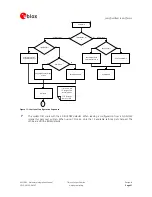
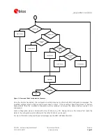
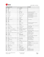
For
USB
devices:
Is
the
voltage
VDDUSB
within
the
specified
range?
Do
you
have
a
Bus
or
Self
powered
setup?
Compare
the
peak
current
consumption
of
AMY-5M
with
the
specification
of
your
power
supply.
GPS
receivers
require
a
stable
power
supply.
Avoid
serial
resistance
in
your
power
supply
line
to
minimize
the
voltage
ripple
on
V_DCDC
and
VDD_3V
(<50mVpp).
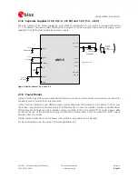
Backup Battery
For
achieving
a
minimal
Time
To
First
Fix
(TTFF)
after
a
power
down,
make
sure
to
connect
a
backup
battery
to
V_BCKP.
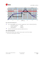
Antenna
The
total
antenna
noise
figure
should
be
well
below
3dB.
If
a
patch
antenna
is
the
preferred
antenna,
choose
a
patch
of
at
least
15x15mm.
For
smaller
antennas
an
LNA
with
a
noise
figure
<2dB
is
recommended,
this
can
increase
sensitivity
up
to
2dB.
To
optimize
TTFF
make
use
of
u-blox’
free
aiding
services
AssistNow
Online
and
AssistNow
Offline.
Make
sure
the
antenna
is
not
placed
close
to
noisy
parts
of
the
circuitry.
(e.g.
micro-controller,
display,
etc.)
To
optimize
performance
in
environments
with
out-band
jamming
sources,
use
an
additional
SAW
filter.
For
more
information
dealing
with
interference
issues
see
the
GPS
Antenna
Application
Note
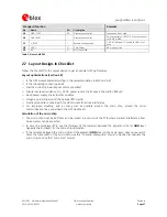
[6].
Schematic
Plan
use
of
2
nd
interface
(Testpoints
on
serial
port,
DDC
or
USB)
for
firmware
updates
or
as
a
service
connector.
For
optimal
power
consumption
run
AMY-5M
in
ECO
power
mode
connect
Pin
PIO21/CFG_GPS0
to
GND.
Pin
PIO23/CFG_GPS2
must
be
connected
to
GND.
V_RESET
connected
to
VDD_3V
unless
an
external
reset
is
required.
For
a
3V
single
power
supply
connect
V_TH
to
GND.
PIO4/RxD1,
PIO7/EXTINT0,
PIO8/EXTINT1
require
external
pull-up
resistors
to
V_DDIO
if
used.
If
not
used,
connect
to
GND.
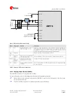
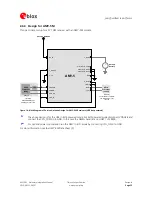
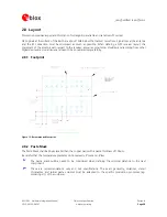
2.6.2 AMY-5M Design
For
a
minimal
Design
with
AMY-5M
the
following
functions
and
pins
need
to
be
considered:
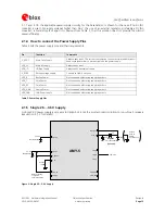
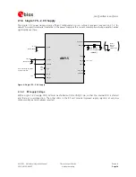
•
Connect
the
Power
supply
to
VDCDC,
VDD_IO,
VDD_3V,
V_BCKP.
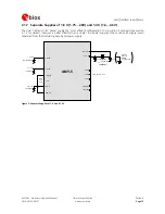
•
VDDUSB:
Connect
the
USB
power
supply
to
a
LDO
before
feeding
it
to
VDDUSB
and
VDCDC
or
connect
to
GND
if
USB
is
not
used.
•
Ensure
an
optimal
ground
connection
to
all
ground
pins
of
the
AMY
module
•
Choose
the
required
serial
communication
interface
(USART
USB,
SPI
or
DDC)
and
connect
the
appropriate
pins
to
your
application
•
If
you
need
Hot-
or
Warmstart
in
your
application,
connect
a
Backup
Battery
to
V_BCKP
and
add
RTC.
•
Decide
whether
TIMEPULSE
options
are
required
in
your
application
and
connect
the
appropriate
pins
on
your
module
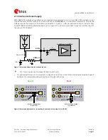
•
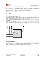
AMY-5M
modules
do
not
provide
the
antenna
bias
voltage
for
active
antennas
on
the
RF_IN
pin.
It
is
therefore
necessary
to
provide
this
voltage
outside
the
module
via
an
inductor
as
indicated
in
Section
2.1.10.


