

AMY-5M
-
Hardware
Integration
Manual
Objective
Specification
Design-In
GPS.G5-MS5-08207
u-blox
proprietary
Page 20
your position is our focus
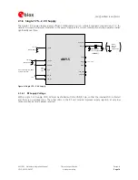
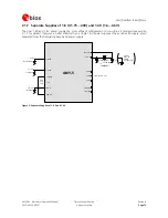
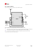
2.3.4 Synchronous Peripheral Interface (SPI)
The
SPI
interface
allows
for
the
connection
of
external
devices
with
a
serial
interface,
e.g.
EEPROM
or
A/D
converters,
or
to
interface
to
a
host
CPU.
The
interface
can
only
be
operated
in
slave
mode.
For
more
information
refer
to
the
Serial Peripheral Interface (SPI) Application Note
[5].
Master
Mode
is
not
supported.
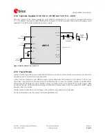
2.4 I/O Pins
2.4.1 Peripheral Input Output (PIO)
All
PIOs
have
internal
pull-ups
or
pull-downs
(PIO9
only).
Thus
there
is
no
need
to
connect
PIOs
to
GND
or
VDD
if
not
used.
Exceptions
from
this
general
rule
are
pins
RXD1,
EXTINT0
and
EXTINT1.
A
signal
change
on
pins
RXD1,
EXTINT0,
or
EXTINT1
can
also
be
used
to
wake
up
the
receiver
from
Sleep-
or
Backup
Mode.
Pins
RXD1,
EXTINT0,
and
EXTINT1
are
powered
by
the
backup
domain
(VDD_B).
These
pins
do
not
have
any
built-in
pull-up
or
pull-down
resistors.
If
these
pins
are
not
used
they
should
be
connected
to
VDD_B
or
to
GND.
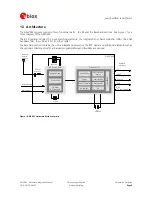
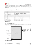
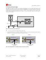
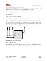
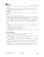
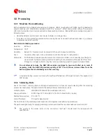
If
they
may
be
undefined
during
operation
they
should
be
connected
with
330
kOhms
resistors
(R8,
R9,
R10)
to
the
upper
rail
of
the
input
voltage
(usually
VDD_IO).
AM Y-5
EXTINT1
EXTINT0
VDD_IO
VDD_IO
R9
VDD_IO
VDD_IO
R10
RXD1
VDD_IO
R8
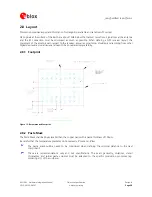
Figure 10: External pull-ups on RXD1, EXTINT0, EXTINT1
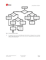
2.4.2 Configuration
Pins
AMY-5M
modules
provide
nine
pins
for
boot-time
configuration.
These
pins
become
effective
immediately
at
start-up.
Care
needs
to
be
used
when
connecting
these
pins,
since
they
can
affect
the
configuration
and
function
of
the
module.
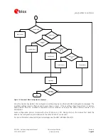
Figure
11
shows
the
sequence
of
configuration
at
boot-time.


