


TLM, TLF, TLD
Page 12
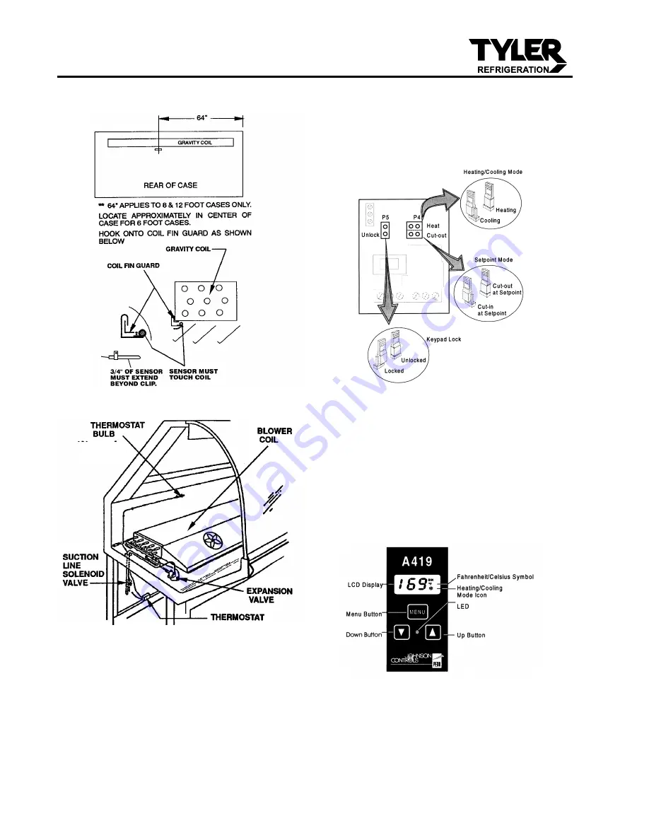
2. Connect sensor wires to the common
(COM) and sensor (SEN) terminals of the
terminal strip located at the top left of the
printed circuit board. The sensor leads
are interchangeble.
3. Set the Heating/Cooling jumper blocks to
the “COOL” position.
4. Set the Cut-in at Setpoint/Cut-out at
Setpoint jumper blocks to the “Cut-out at
Setpoint” position.
5. Set the Keypad Locked/Unlocked jumper
blocks to the “Unlocked” position.
6. Replace the electronic thermostat cover
and secure with four screws.
7. To adjust the setpoint:
a. Push the Menu Button. “SP” will flash
on the LCD display.
b. Push the Menu Button one more time
and a setpoint temperature will be
displayed.
Typical Service Case with Blower Coil
In addition to the thermostat and suction
solenoid, a suction stop EPR valve is
required in the suction line. The EPR
valve acts as a low pressure limit to aid
in the overall temperature control. See
“Connecting the Refrigeration Piping and
Components” on page 27 of this manual.
Setting the Electronic Thermostat
1. Remove the four screws and cover from
the electronic thermostat.
THERMOSTAT BULB PLACEMENT
April, 2007
Содержание Allegro TLD
Страница 5: ...Installation Service Manual TLM TLF TLD Page 5 April 2007 ...
Страница 6: ...TLM TLF TLD Page 6 April 2007 ...
Страница 14: ...Page 14 TLM TLF Domestic Export 50 Hz Case Circuits 4 6 8 and 12 Cases July 2005 ...
Страница 15: ...Page 15 July 2005 ...
Страница 16: ...Page 16 July 2005 ...
Страница 17: ...Page 17 July 2005 ...
Страница 18: ...Page 18 TLD Domestic Export 50 Hz Case Circuits 4 6 8 and 12 Cases July 2005 ...
Страница 19: ...Page 19 July 2005 ...
Страница 20: ...Page 20 July 2005 ...
Страница 21: ...Page 21 July 2005 ...


