background image

L A S E R S   F O R   M A R K I N G

Machine Overview

Your Zetalase™ comes configured as a Class I Laser Marking System ready for 
marking right out of the box.   Each system is configurable based on application and 
laser type so please check your order confirmation for exact system configuration.  
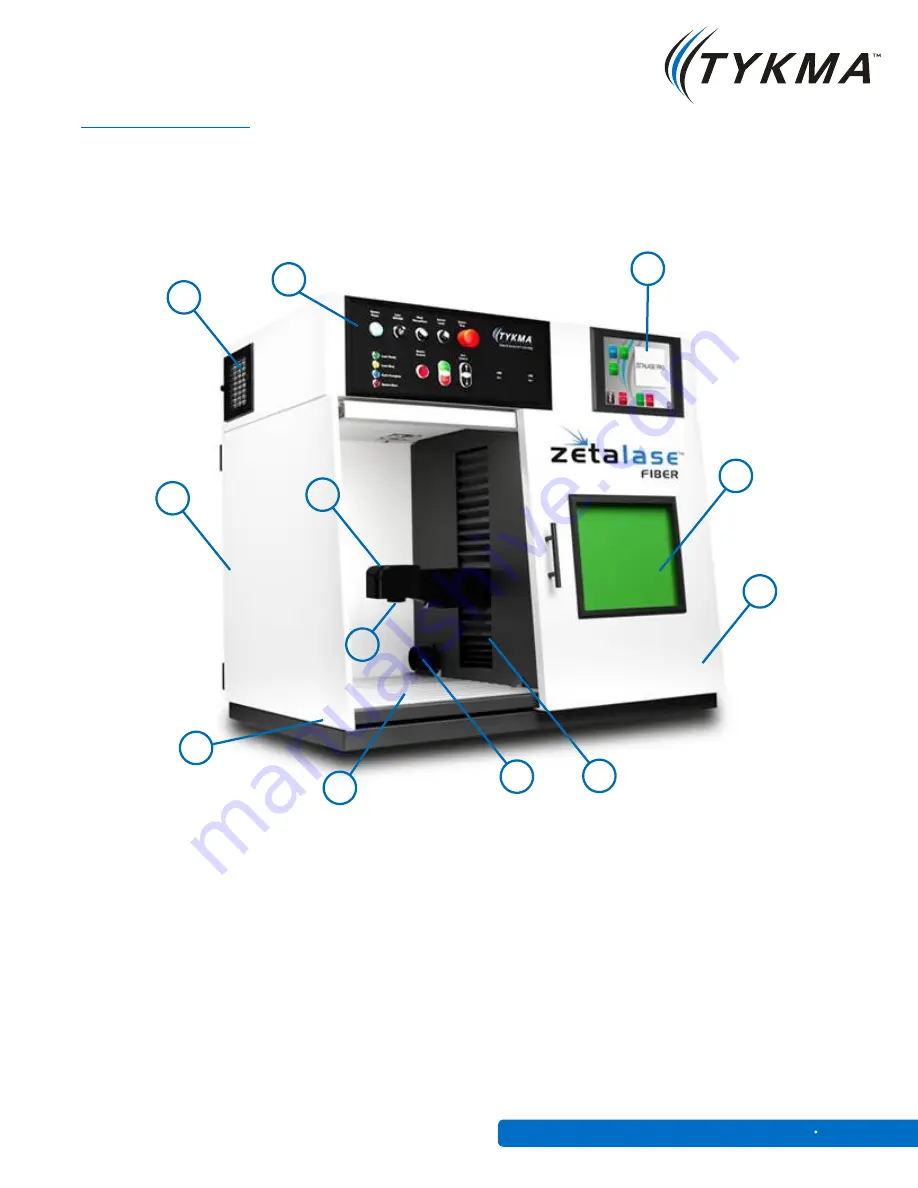
Please reference the below diagram for identification of components and terms 
used in this manual.

4

3

12

7

5

1

2

6

9

10

11

8

Laser Scan Head

Focusing Lens

Operator Control Pendant

Touchscreen Interface

Sliding Operator Door

Laser Safety Glass Viewing Window

Side Access Door

Door Interlock

T-Slot Toolplate

Adjustable Z-Axis

Fume Extraction Port

Cooling Fan

1) 

2) 

3) 

4) 

5)

6) 

7) 

8) 

9) 

10) 

11) 

12)


Zetalase

15

General Manual SE 1

Содержание Zetalase

Страница 1: ...L A S E R S F O R M A R K I N G General Manual ...

Страница 2: ...ks of the Microsoft Corporation They are only used in this document for editorial purposes All information and contents in this document are property of TYKMA Inc and cannot be shown distributed modified and or reproduced through electronic mechanical or any other way without written consent from TYKMA Inc Originally Published January 2013 TYKMA Technologies P O Box 917 931 E Water Street Chillico...

Страница 3: ...cations Laser Safety Introduction Machine Overview System Setup Operator Pendant System Operation Maintenance L A S E R S F O R M A R K I N G Zetalase General Manual SE 1 3 1 2 3 4 5 6 7 8 9 Contents 3 4 5 14 15 16 18 20 24 Page ...

Страница 4: ...ith Safety Key Lock Shutter Start E stop Operator HMI for Quick Program Select and Part Changeover 10 Touch Screen Integrated Monitor External Keyboard Mouse USB Network Monitor Ports Integrated Focus Finder Class 1 Safety Interlocking 100 240V one plug operation Laser programming software included Air Cooling Max part height 9 5 with FL160 S lens 5 5 with FL254 S lens Dimensions 40 W x 26 D x 35 ...

Страница 5: ...pectrum Ultraviolet radiation for lasers consists of wavelengths between 180 and 400 nanometers nm The visible region consists of radiation with wavelengths between 400 and 700 nm This is the portion we call visible light The infrared region of the spectrum consists of radiation with wavelengths between 700 nm and 1 mm The color or wavelength of light being emitted depends on the type of lasing ma...

Страница 6: ...f fumes and gases Sometimes these gases are noxious or even toxic Fumes from laser marking should be controlled with an adequate fume extraction system When in doubt a chemical analysis of the fumes is suggested to determine if any fume hazards exist Laser systems are typically designed to prevent a beam from directly contacting a person Risks therefore are more a result of unintentional reflected...

Страница 7: ... and focused onto the retina Exposure may initially go undetected because the beam is invisible and the retina lacks pain sensory nerves Visual disorientation due to retinal damage may not be apparent to the operator until considerable thermal absorption has occurred Since the energy is concentrated by the eye s lens the strength of the laser beam that is required to damage the eye is significantl...

Страница 8: ...ild reddening to blisters and charring These conditions are usually repairable or reversible However de pigmentation ulceration scarring of the skin and damage to underlying organs may occur from extremely high powered lasers The MPE is defined in ANSI Z 136 1 1993 as The level of laser radiation to which a person may be exposed without hazardous effect or adverse biological changes in the eye or ...

Страница 9: ...l measures include Engineering controls include proper shield interlock designs when required and safe system operation controls as in situations where the laser will be integrated into another control system The use of lasers or laser systems can present an electric shock hazard This may occur from contact with exposed utility power utilization device control and power supply conductors operating...

Страница 10: ... regard to the wavelength of the laser light and where appropriate the wavelength of any light emitted from the material surface during the marking process Table 2 Optical Densities for Protective Eyewear for Q Switched Nd Yag L A S E R S F O R M A R K I N G Laser Type Power Wavelength m OD 0 25 seconds OD 10 seconds OD for 600 seconds OD for 30 000 seconds Nd YAG Q switch b 1 064a 4 5 5 0 5 4 Zet...

Страница 11: ... K I N G Control Measures Classification Engineering Controls 1 2a 2 3a 3b 4 Protective Housing X X X X X X Without Protective Housing Laser Safety Officer establishes alternative controls Interlocks on protective housing X X Service Access Panel X X Key Control X Viewing Portals MPE MPE MPE MPE Collecting Optics MPE MPE MPE MPE MPE MPE Totally Open Beam Path X NHZ X NHZ Limited Open Beam Path X N...

Страница 12: ...ating Procedure X Output Emission Limitations LSO Determines Education and Training X X Spectator Controls X Service Personnel MPE MPE MPE MPE X X Laser Fiber Optic Systems MPE MPE MPE MPE X X Eye Protection MPE X MPE Protective Windows X NHZ X NHZ Protective Barriers and Curtains Skin Protection X MPE X MPE LEGEND X shall should no requirement NHZ NHZ analysis required shall if enclosed Class 3b ...

Страница 13: ...A S E R S F O R M A R K I N G and interlock defeated Universal Laser Warning Sign EXPOSURE TO THE LASER BEAM MAY CAUSE PHYSICAL BURNS AND CAN CAUSE SEVERE EYE DAMAGE Proper use and care of this system are essential to safe operation Danger Sign Exposure to the laser beam possible when interlocks are defeated EXPOSURE TO THE LASER BEAM MAY CAUSE PHYSICAL BURNS AND CAN CAUSE SEVERE EYE DAMAGE Univer...

Страница 14: ... installed separately First unscrew the crate side panels and packing Using a pallet jack or fork lift raise the pallet carefully and move it to the work area Zetalase is a tabletop or workbench system so you will need a sturdy 40 wide x 26 deep workbench with the following access area at least 70 of headroom and an additional 180 radius of 26 on the left side of the system to accommodate access d...

Страница 15: ...ation for exact system configuration Please reference the below diagram for identification of components and terms used in this manual 4 3 12 7 5 1 2 6 9 10 11 8 Laser Scan Head Focusing Lens Operator Control Pendant Touchscreen Interface Sliding Operator Door Laser Safety Glass Viewing Window Side Access Door Door Interlock T Slot Toolplate Adjustable Z Axis Fume Extraction Port Cooling Fan 1 2 3...

Страница 16: ...f the door Pull upward on the pin to release the interlock and make sure the door swings fully to the left The top of the door is held in place by tension fit To open the door apply pressure L A S E R S F O R M A R K I N G Step 1 Side Access Door Removal The side door can also be removed to provide full access to the T Slot bedplate for tooling and fixture modifications or adjustments To remove th...

Страница 17: ...recommended to network your PC for online service and support capability with one of TYKMA s experienced technicians STEP 5 Connect the supplied Power Cord to the Input Power port Plug in the other end of the Power Plug into a Power Strip with Surge Protection TYKMA highly recommends the use of surge protection for safe operation of your laser marking system STEP 6 Power ON your system by pressing...

Страница 18: ...Fiber models 6 1 System Power Laser Enable Key Switch Auto Manual Mode Selector Switch Interior Lamp Emergency Stop Laser Status Indicator Shutter Open Close Manual Start Stop Z Axis Up Down or Overtravel Bypass USB Ports for Embedded PC 1 2 3 4 5 6 7 8 9 10 2 3 4 5 7 8 9 10 On Automatic Z Axis Models Zetalase 18 General Manual SE 1 ...

Страница 19: ...lase Status Indication Green Laser Ready Yellow Laser Busy Marking Complete System Fault Shutter Push Open Close Shutter is open when pressed and doors are closed with safety interlocks engaged Start Stop Starting or stopping the laser process in Manual mode Axis Control On standard Zetalase models this will move laser Z Axis UP Down On optional Automatic Z Axis models this is an overtravel bypass...

Страница 20: ...C has booted to the Windows Desktop Insert a Laser Enable Key into the Laser OFF ON switch and turn it to the RIGHT Please wait 5 10 seconds for the laser to warm up Should you wish to protect the system from unauthorized operation simply remove the Laser Enable Key and store in a safe location when not in use Step 1 2 Power ON Laser Enable 2 1 Zetalase 20 General Manual SE 1 ...

Страница 21: ...YKMA Service Support 1 877 318 9562 STEP 5 Focus the Laser For a Power Z axis press the up and down arrows on the Operator Pendant until the focusing beams converge For an Automatic Programable Z axis click Part Height and type in the height of your part and then click Trace The Z axis will then move to the correct focal position Step 3 Open Minilase Pro SE Zetalase 21 General Manual SE 1 Step 5 P...

Страница 22: ...chine Move your part or move the mark to align to the desired location When completed with alignment click Stop to close the screen Please refer to the Minilase Pro SE Software Manual for instructions on creating graphics and configuring laser settings STEP 7 Marking with the Laser To mark with the laser close the door press Start or click the Mark F2 button this will start the marking for all act...

Страница 23: ... After clicking Mark a pop up window will appear and the Laser will be marking Laser Busy will be indicated on the operator pendant and Cycle Complete will illuminate when the marking is finished Click Stop only if there is something wrong with your marking Zetalase 23 General Manual SE 1 ...

Страница 24: ...y be required in dirty oily environments See Cooling Fan Filter Replacement procedure Laser Lens The focusing lens on your laser should be cleaned once every 3 months shorter intervals may be required in dirty oily environments See Laser Lens Cleaning procedure Z Axis Lubrication The Motor Driven Z Axis should be lubricated with Velmex BL 1 oil a minimum of once a year See Z Axis Lubrication proce...

Страница 25: ... The cooling fan on the upper left side pane above the access door has a removable cover Push down and out on the fan cover to gain access to the replaceable filter media See picture below Step 1 Step 2 Filter PN 11720003055 Manufacturer pfannenberg Order from TYKMA or direct Zetalase 25 General Manual SE 1 ...

Страница 26: ...on the Zetalase should be cleaned once every 3 months shorter intervals may be required in dirty oily environments Use a mixture of 90 water 10 Acetone to clean the lens using a lint free cloth Visually inspect the lens for cleanliness and scratches or cracks Zetalase 26 General Manual SE 1 ...

Страница 27: ...Z Axis you must remove the right service panel of the Zetalase by removing the 4 bolts shown below Remove the side access panel and set aside See Velmex lubrication illustration for details on lubricating the Z Axis below Remove 4 Bolts Metric Allen Wrench Lubricate Z Axis Both Screw Rails Lubrication PN BL1 Manufacturer Velmex Order from TYKMA or direct Zetalase 27 General Manual SE 1 ...

Страница 28: ...L A S E R S F O R M A R K I N G TYKMA Technologies P O Box 917 931 E Water Street Chillicothe OH 45601 Toll Free 877 318 9562 Fax 740 779 9910 ...

Отзывы: