background image

3


STEP 5:  

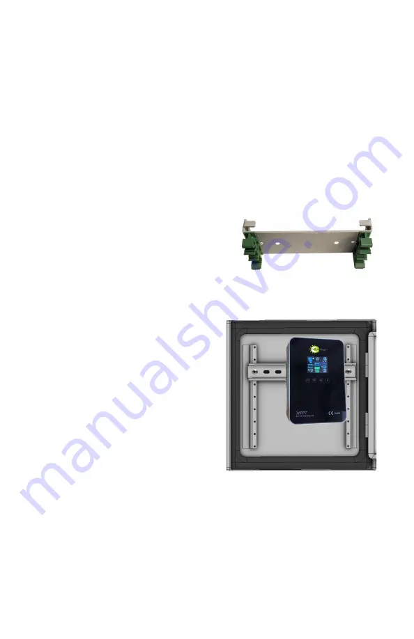
Attach the included DIN Rail to the door using hardware pro-

vided.


STEP 6: 

Install 4 cable feedthroughs to the bottom of the enclosure.


TIP: 

There are multiple cable gland feedthrough in the bottom of the 

enclosure. If you are not using any of the feedthrough you can cut a 

short piece of wire, put it through the cable gland and tighten the cable 

gland on the wire to seal it.


STEP 7: Remove the fuse from the battery cable(s)

 and connect 

wires to the batteries, then install the batteries. 


STEP 8: 

Attach the green DIN Rail clips to the MPPT controller bracket 

using screws provided and attach the bracket to the controller. The ex-

tra parts aren

t used. Remove the small plate on the controller back to 

access the wire terminal screws. Connect 

the battery wires and the wires from the 

PowerVent

™ 

fan  to the controller battery 

input for 12V or 24V battery configuration 

and directly to one or two of the batteries 

if 48V configuration. Be sure to observe 

proper polarity. (RED=+). 


CAUTION: 

Reverse polarity connections will damage the equip-

ment.


STEP 9: 

Connect the included solar 

panel cable to the MPPT controller PV 

inputs (Red to PV+). Don

t connect  

the solar cable to solar panel connect-

ors until the controller is connected to 

the batteries. 


STEP 10: 

Connect your load to the 

MPPT Controller load output. When 

the MPPT controller is energized with 

full battery voltage the load will turn on 

automatically.


STEP 11: 

Replace the wire terminal 

access door on the back of the MPPT 

controller and mount the MPPT con-

troller to the DIN rail mounted on the enclosure door.


STEP 12:

  Double check wiring and then re

-

install the battery cable 

fuse to energize the system. The MPPT controller will power up and 

automatically detect the battery configuration. The display is activated 

by vibration, so to turn on the display, tap the glass cover. Once the 

controller is energized, connect the solar panel connectors to the solar 

cable coming from the MPPT controller PV input.


CAUTION: 

Reverse polarity connections will cause damage.


Содержание RemotePro RPSTL 12

Страница 1: ...ith overhead power lines lights and power circuits Contact with power lines lights or power circuits may be fatal We rec ommend to install no closer than 20 feet to any power lines Safety For your own protection follow these safety rules Perform as many functions as possible on the ground Do not attempt to install on a rainy windy or snowy day or if there is ice or snow accumulation at the install...

Страница 2: ... Solar panels should face south if you are in the northern hemisphere When mounting the enclo sure be sure to mount low enough so the door of the enclosure clears the solar pan els when opened We suggest mounting the enclosure so it is shaded by the panels during the day STEP 2 Attach the solar panels to the solar panel mount so that the wire junction box is towards the top or side Connect the sol...

Страница 3: ...he batteries if 48V configuration Be sure to observe proper polarity RED CAUTION Reverse polarity connections will damage the equip ment STEP 9 Connect the included solar panel cable to the MPPT controller PV inputs Red to PV Don t connect the solar cable to solar panel connect ors until the controller is connected to the batteries STEP 10 Connect your load to the MPPT Controller load output When ...

Страница 4: ...anging this to a fixed 24V if using a 24V battery configuration or fixed 48V if using 48V configuration so that the system can recover automatically if by chance the batteries get drained completely See MPPT controller user manual for specific instructions STEP 13 Make sure lid gasket is clean and free from any particles then carefully close the cover making sure that wires are clear of the seam a...

Страница 5: ...5 720W Two Panel Configuration for 12V or 24V or 48V Battery Configurations 1440W Four Panel Configuration for 24V or 48V Battery Configurations ...

Страница 6: ...6 CAUTION Be sure to connect the battery to the controller first and dis connect it last Connecting solar panels to the controller without the bat tery connected could damage the controller ...

Страница 7: ...7 ...

Страница 8: ...8 ...

Страница 9: ...r a long time in a discharged state or it will kill the battery Especially in cold temperatures 6 Remote Monitoring There is an RS485 port on the MPPT control ler This port is a special port to interface to the Tycon TPDIN Monitor WEB3 V2 using a TPDIN CABLE 485 cable for remote monitoring via Ethernet The RS485 port can also be used with the Tycon TP SC WiFi to pro vide connectivity to a wireless...

Страница 10: ...t efficient operation is achieved by wiring 12V or 24V panels in series On 24V panels the controller can only handle two panels in series because four 24V panels in series would exceed the controller max voltage So in 4 panel configurations wire the panels in series parallel configuration C My system turns off at night and comes back on in the morn ing This is a sure sign that the solar panels and...

Страница 11: ...d AGM Battery Life 5 Years Controller Type 60A MPPT Temperature Compen sated Over Voltage Protection 16V 32V 64V Bulk Charge 14 4V 28 8V 57 6V Float Charge 13 8V 27 6V 55 2V Over discharge protection 11 1V 22 2V 44 4V Over discharge recovery volts 12 6V 25 2V 50 4V Controller Self Consumption 1W Enclosure Type Powder Coat Steel Wind Survivability 90MPH Operating Temperature 30 C to 60 C 12 24V 60A...

Страница 12: ...per installation misuse poor site conditions faulty power etc Lightning or weather damage Physical damage to the external internal parts Products that have been opened altered or defaced Water damage for units that were not mounted according to user manual Usage other than in accordance with instructions and the normal intended use Tycon Systems 14641 S 800 W Bluffdale UT 84065 support tyconsystem...

Отзывы: