TFP1253
Page 6 of 8
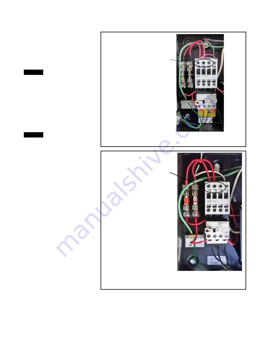
460 VAC/3 PHASE/60 HZ OR
208 VAC/3 PHASE 60 HZ CONNECTIONS
LANDING POINTS
LABELED L1, L2, L3
The air compressors come with pre-
punched holes in the feet for easy
mounting to the floor using standard
anchors.
Note:
Vibration pads (supplied) must be
installed under the feet of the air compressor
to ensure warranty of the air compressor.
Step 2. Power Supply
NOTICE
It is recommended that a service dis-
connect be provided adjacent to the air
compressor.
The air compressors require a dedi-
cated power supply that is terminated
in the power supply box on the air com-
pressor as shown in Figure 3A, 3B, or
3C as applicable. Verify the voltage
of the power supply available for the
air compressor is compatible with
the voltage requirements of the air
compressor.
NOTICE
With the TNGC-1500/2000 and the
TNGC-3000, verify that the compres-
sor and motor starter are configured
for operating at 208 VAC/3 phase
when providing 208 VAC/3 phase to
the control box.
Step 3: Plumb the Air Supply Line
For compressors in the Americas, the
air discharge plumbing from the air
compressor is to be connected to the
inlet of the nitrogen generator using
1/2 in. black steel, galvanized steel or
copper lines. For compressors in EMEA
and APAC, the air discharge plumb-
ing should first be connected to the
WSD-25 water separator which then is
to be connected to the inlet of the nitro-
gen generator.
Step 4: Plumb the Condensate
Drain Line
The TYCO oil-less air compressor will
discharge condensate water from the
air receiver tank. It is recommended
that the 1/4 in. drain connection be
plumbed to a floor drain or building
exterior. When plumbing to a drain is
not feasible an evaporative collection
chamber can be used.
Note:
Ensure that the receiver tank auto-
drain is connected to an un-switched power
source: 120 VAC for Americas, 230 VAC for
EMEA and APAC.
Note:
The Low Oil Level Sensor on the air
compressor automatically shuts down air
compressor until the proper oil level has
been restored.
Care and
Maintenance
Nitrogen Generators
The TYCO NG-1 1150, NG-1 1500, NG-1
2000, and NG-1 3000 Stand-Alone
Nitrogen Generators, the TNGC-1150
Air Compressor, and TNGC-1500/2000
and 3000 Air Compressors must be
maintained and serviced in accordance
with this section.
Before closing a fire protection system
main control valve for maintenance
work on the fire protection system that
460 VAC/THREE PHASE/60 HZ OR
208 VAC/THREE PHASE/60 HZ
CONNECTIONS
LABELED L1, L2, L3
FIGURE 3A
MODEL TNGC-1150 AIR COMPRESSOR
AMERICAS POWER SUPPLY CONNECTIONS
FIGURE 3B
MODEL TNGC-1500/2000/3000 AIR COMPRESSOR
AMERICAS POWER SUPPLY CONNECTIONS


