408-8974
MRJ21 24-Port 10/100/1000BASE-T Straight Patch Panels 1777029-[ ]
Rev D
2 of 2
Tyco Electronics Corporation
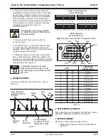
2. Plug a connector (from the trunk cable) into
each MRJ21 receptacle (at the back of the patch
panel). Refer to Figure 2. Make sure to align the
keying features of the connector and receptacle.
Ensure that the connector is fully seated,
then
using a small cross–recessed tipped screwdriver,
turn the jack screws of the connector
clockwise
and tighten to a maximum torque of
0.23 Nm [2 lbf–in.].
To avoid damage to the connector, DO NOT
over-tighten the jack screws. DO NOT use an
automaticscrewdriver.
3. Using the blank label pads, identify the
connecting ports.
4. For Patch Panel –2, plug the connector of the
I/O cable assembly (PN 1499507–[ ]) from the
analyzer into the HDP–22 connector (at the back of
the patch panel). See Figure 2.
5. Install the bracket onto the rack. Using cable
ties or similar fasteners, attach the cables to the
bracket. It is recommended to maintain a minimum
bend radius of 50.8 mm [2 in.] when securing and
routing cables. See Figure 2.
For installation procedure for the wiring
distribution bracket, refer to Figure 2; for the
back cable manager, refer to Instruction Sheet
408-10170.
4. TROUBLESHOOTING
For port–to–cable pair cross–reference, refer to
Figure 3.
Figure 2
Trunk
Cable
Bracket
(Ref)
Connector Plugged
into MRJ21 Connector
(4 Places)
Cable
Tie
Front of
Patch Panel
Connector Plugged
into HDP-22 Connector
(Patch Panel -2 Only)
EIA Rack
(Ref)
2
3
4
5
6
16 RJ45 Connector Assembly
(Front of Patch Panel)
1
MRJ21 Receptacle
(Back of Patch Panel)
Pair 1
Pair 3
Pair 2
Pair 4
8
9 10 11 12
7
14 15 16 17 18
13
20 21 22 23 24
19
3
5
1
4
6
2
Note: For Reference, Ports Labeled 1 Through 6 Are Shown
Pair 6
Pair 5
Pair 8
Pair 7
PORT
CABLE PAIRS
(4 Pairs Per Port)
1
13
1, 2, 3, 4
2
14
5, 6, 7, 8
3
15
9, 10, 11, 12
4
16
13, 14, 15, 16
5
17
17, 18, 19, 20
6
18
21, 22, 23, 24
7
19
1, 2, 3, 4
8
20
5, 6, 7, 8
9
21
9, 10, 11, 12
10
22
13, 14, 15, 16
11
23
17, 18, 19, 20
12
24
21, 22, 23, 24
Figure 3
5. REPLACEMENT AND REPAIR
Patch panels are not repairable. DO NOT use a patch
panel with damaged or defective connectors.
6. REVISION SUMMARY
Revisions to this instruction sheet include:
S
Added text to Steps 2 and 5 and CAUTION of
Section 3
CAUTION
!
NOTE
i


