background image

40

Chapter 3: Replacing Pre-Installed Components

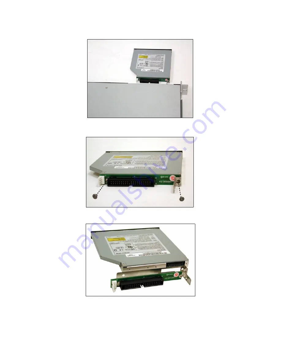
3. The CD-ROM drive will be freed from the drive bay after 

pressing the tab.

4. Remove two screws that secure CD-ROM drive to the 

bracket.

5. Replace the CD-ROM drive.

6. Secure CD-ROM to the bracket using two screws. Then 

replace the unit into the drive bay and connect the CD-
ROM power and data cables.

Содержание Transport GT20 B5151

Страница 1: ...Transport GT20 B5151 Service Engineer s Manual...

Страница 2: ......

Страница 3: ...anges to product descriptions and or specifications at any time without notice In no event will TYAN be held liable for any direct or indirect incidental or consequential damage loss of use loss of da...

Страница 4: ...ent into an outlet on a circuit different from that of the receiver Consult the dealer on an experienced radio television technician for help Notice for Canada This apparatus complies with the Class B...

Страница 5: ...a table of key compo nents and provides block diagrams of the system Chapter 2 Covers procedures on installing the CPU mem ory module PCI X card and hard drive Chapter 3 Covers removal and replacemen...

Страница 6: ...this pin If your outlet does not support this kind of plug contact your electrician to replace your obsolete outlet Do not place anything on the power cord Place the power cord where it will not be i...

Страница 7: ...Motherboard Components 19 2 2 1 Removing the Chassis Cover 19 2 2 2 Installing the CPU Heatsink and Air Duct 20 2 2 3 Installing the Memory 24 2 2 4 Installing a PCI Card 25 2 3 Installing the Hard D...

Страница 8: ...Fan Layout 46 3 7 3 M1010 Adapter Board Connector Pin Definition 48 3 8 Replacing the SATA Backplane 53 3 8 1 SATA Backplane Features 55 3 9 Replacing the Power Supply 57 Appendix I BIOS Differences...

Страница 9: ...a lightning fast PCI X bus implementation The TransportTM GT20 B5151 not only empowers your company in today s demanding IT environment but also offers a smooth path for future application usage TYAN...

Страница 10: ...ts Front Panel Features I O 2 USB 2 0 ports LED indicators One HDD LED One LAN LED One Power LED Switches Power switch Reset switch Harware Monitoring Smart auto fan speed control Fan Monitoring CPU T...

Страница 11: ...AN s Web site for service http www tyan com The Web site also provides information on other TYAN prod ucts plus FAQs compatibility lists BIOS settings and more FDDs 1 x Tyan driver CD SMDC Kit Power C...

Страница 12: ...4 Chapter 1 Overview Mainboard Manual Barebone Manual Heatsink x 1 Rail Kit Mounting Bracket x 4 Screws Kit Front Rear Sliding Brackets Front L Bracket x 2 Rear L Bracket x 2 Sliding Rails x 2...

Страница 13: ...rved reserved for future upgrade 1 4 2 Rear View CD ROM Drive Hard Drive Bay x 4 HDD activity LED Power switch Power LED Reset switch USB ports Warning LED LAN LED Reserved Power Supply Socket PS 2 Mo...

Страница 14: ...ay Power LED Green OFF ON OFF Power connected Power disconnected Hot Swappable HDD Tray Access LED Reserved LED for future upgrade It is not functional in the B5151 barebone now LED Color State Descri...

Страница 15: ...erview 7 NOTE Right or Left is viewed from the rear RJ45 NIC3 Linkage Left Side Green Green OFF ON Blinking OFF LAN linked LAN accessing No LAN linked RJ45 NIC3 Mode Right Side Green OFF ON OFF 100M m...

Страница 16: ...lot 2 Link Bar 3 Memory Slots 4 EPS 12V Power Supply 5 Air Duct 6 System Fans Left to right FAN5 FAN4 FAN3 FAN2 FAN1 7 Adapter Board 8 SATA Backplane 9 LED Control Board Cable 10 Tyan TARO Connector 1...

Страница 17: ...Chapter 1 Overview 9 1 4 5 Motherboard Block Diagram...

Страница 18: ...PCI Express 32 bit 33MHz 5V PCI IDE J17 X1 PCI Express SO DIMM J 25 P JP24 JP26 LPT FDD JP4 JP5 JP6 JP7 JP2 BROADCOM 5721 BROADCOM 5721 JP1 JP13 JP12 JP15 SATA1 SATA3 JP15 SATA4 SATA2 SMDC JP16 JP18 J...

Страница 19: ...N2 LAN1 LAN3 disabled headers JP4 JP7 Front panel LAN1 LAN2 speed LED pin headers JP5 JP6 Front panel LAN1 LAN2 link and active LED connec tors JP8 Chassis fan connector JP20 SMDC connector JP12 JP13...

Страница 20: ...12 Chapter 1 Overview Memo...

Страница 21: ...ntainers to keep small components separated Putting all small components in separate containers prevents them from becoming lost Adequate lighting and proper tools can prevent you from accidentally da...

Страница 22: ...of any other grounded appliance Avoid touching motherboard components IC chips connectors memory modules and leads The motherboard is pre installed in the system When removing the motherboard always p...

Страница 23: ...t GT20 B5151 into an industry standard 19 rack NOTE Before mounting the Transport GT20 in a rack ensure that all internal components have been installed and that the unit has been fully tested Mainten...

Страница 24: ...lied screws kit to secure the sliding rail to the bracket 3 Slide each sliding rail to the side of Transport GT20 as shown 4 Using two screws from the supplied screws kit to secure the sliding rail to...

Страница 25: ...g bracket from the supplied kit Screw the bracket to rack using 2 screws for each side Be care ful that the mounting bracket should be secured from the inside not outside of rack See the picture below...

Страница 26: ...e rack A Ensure the unit is completely inserted into the rack B Then screw the unit into place as shown C Note To avoid injury it is strongly recom mended that two people lift the Transport GT20 into...

Страница 27: ...tall components on to the motherboard including CPU memory modules and PCI card 2 2 1 Removing the Chassis Cover Follow these instructions to remove the Transport GT20 chassis cover 1 Release the scre...

Страница 28: ...2 Installing the CPU Heatsink and Air Duct Follow these instructions to install the CPU CPU heatsink and air duct 1 Release the pre installed air duct Then locate the CPU socket 2 Remove the cover on...

Страница 29: ...Chapter 2 Setting Up 21 3 Locate the lever of CPU socket 4 Press the lever in the direction as shown to release the CPU socket 5 Pull the lever in the direction...

Страница 30: ...6 Open the CPU socket 7 Place CPU on the socket ensuring that the edge with tri angle mark aims at the edge of socket with triangle mark 8 Close the cover and secure the CPU socket in the reverse proc...

Страница 31: ...Chapter 2 Setting Up 23 9 Secure the heatsink using 4 screws 10 Secure the air duct using 2 screws Heatsink Screw...

Страница 32: ...modules on the motherboard 1 Locate the memory slots on the motherboard 2 Press the memory slot locking levers in the direction of the arrows as shown in the following illustration 3 Align the memory...

Страница 33: ...s at the ends of the module NOTE When installing memory always install the memory beginning with DIMM4 not DIMM1 That means starting the installation from the memory module near the power supply 2 2 4...

Страница 34: ...Setting Up 2 Move the bracket to right as shown and then take off the bracket 3 Insert the PCI card in the directions of arrow 4 Push the tab of PCI slot on the rear panel in the direction as shown to...

Страница 35: ...rebone system supports Serial ATA hard drives Follow these instructions to install a SATA hard drive 1 Press the locking lever latch in the direction of arrow A and then pull the locking lever open B...

Страница 36: ...ng Up 4 Secure SATA hard drive using 4 screws 5 Reinsert the drive bay into the chassis A ensuring that the drive bay is completely inserted into the chassis B 6 Press the locking lever to secure the...

Страница 37: ...DD Option 1 Locate the two FDD rails and screws from the FDD kit Secure the two rails to FDD using four screws 2 Connect the FFC cable to FDD 3 Using a screw driver to pull open the door of FDD tray 4...

Страница 38: ...tor on M1010 adapter board 6 Locate the FDD cable from FDD kit Connect the wrinkle side to the connector on M1010 adapter board Refer to the picture below for the correct direction 7 Connect the other...

Страница 39: ...ons Use containers to keep small components separated Putting all small components in separate containers keeps them from becoming lost Adequate lighting and proper tools can prevent you from accident...

Страница 40: ...tal body of any other grounded appli ance Avoid touching motherboard components IC chips connectors memory modules and leads The motherboard is pre installed in the system When removing the motherboar...

Страница 41: ...t The following flowchart outlines the disassembly procedure Rear Components Chass rear cover Air duct Mainboard DIMMs CPU heatsink assembly PCI card Mainboard Power supply Front Components FAN PCBs C...

Страница 42: ...Cover Before replacing any parts you must remove the chassis cover Follow these instructions to remove the cover of the Transport GT20 chassis cover 1 Release the screw on the back side Then slide th...

Страница 43: ...emove cables connected to the motherboard Follow these instructions to remove all motherboard cabling 64bit 133 100 66MHz PCI X X1 PCI Express 32 bit 33MHz 5V PCI IDE J17 X1 PCI Express SO DIMM J 25 P...

Страница 44: ...36 Chapter 3 Replacing Pre Installed Components 1 Disconnect ATX power cables 2 Disconnect CD ROM drive cable Main Power EPS 12V Power...

Страница 45: ...Chapter 3 Replacing Pre Installed Components 37 3 Disconnect the cables from SATA FAN and Front Panel connectors 4 Disconnect the LAN LED cables SATA Cables Fan Cables Front Panel Cable...

Страница 46: ...ponents 3 4 2 Removing the Motherboard After removing all cables follow these instructions to remove the motherboard from the chassis 1 Remove the link bar 2 Remove the ten screws securing the motherb...

Страница 47: ...ents 39 3 5 Replacing the Slim CD ROM Follow these instructions to replace the CD ROM 1 Remove power and data cables from the slim CD ROM adapter 2 Press the tab in the directions as shown to release...

Страница 48: ...be freed from the drive bay after pressing the tab 4 Remove two screws that secure CD ROM drive to the bracket 5 Replace the CD ROM drive 6 Secure CD ROM to the bracket using two screws Then replace t...

Страница 49: ...placing the LED Control Board Follow these instructions to replace the LED control board 1 Remove two screws securing LED control board unit to the chassis 2 Lift the LED control board unit free of th...

Страница 50: ...nplug the USB cable from the connector 5 Remove three screws securing LED control board to the bracket 6 Lift the LED control board free from the chassis After replacement insert the unit into the cha...

Страница 51: ...rd 1 Disconnect the cables connectoed to the M1010 adapter baord including Fan PWM Front Panel and LAN ID LED 2 Disconnect the power cables connected to the M1010 adapter board and HDD backplane 3 Dis...

Страница 52: ...44 Chapter 3 Replacing Pre Installed Components 4 Disconnect the five fan cables connected to the M1010 adapter board 5 Remove the six screws securing the M1010 adapter board...

Страница 53: ...ach PWM Connector JP1 Fan Input Select J19 CD ROM Power Connector Connector J5 Fan Connector J9 Fan Connector J11 Fan Connector J10 Fan Connector J2 Front Panel Connector J6 Fan Connector Slim FDD Con...

Страница 54: ...46 Chapter 3 Replacing Pre Installed Components 3 7 2 System Fan Layout The following picture provides the information for system fan layout Refer to the tables on p 47 for information on connec tion...

Страница 55: ...nal System Fan Monitoring Signal NOTE FAN1 doesn t support the Fan Monitor function M1010 Adapter Board Connect to Motherboard J7 PWM Connector P1 Fan Barebone System Fan Connect to Motherboard Fan Fa...

Страница 56: ...R_SW 7 RESET 8 PWR_SW 9 VOLTAGE5 10 WLED 11 EXT_INT 12 WLED 13 V5SB 14 KEY PIN 15 ICH_SMBDAT 16 GND 17 ICH_SMBCLK 18 INTRU 1 HDLED 2 HDLED 3 RESET 4 RESET 5 PW_LED 6 PW_LED 7 WLED 8 WLED 9 ICH_SMBDAT...

Страница 57: ...it design only It might be different from the system fan naming J7 Fan TACH PWM Connector J8 PWM Connector J13 Fan TACH Connector 1 LAN1_LED 2 LAN1_LED 3 LAN2_LED 4 LAN2_LED 5 LAN3_LED 6 LAN3_LED 7 ID...

Страница 58: ...Fan Connector 1 GND 2 FAN4_TACH 3 GND 4 FAN5_TACH 5 GND 6 FAN6_TACH 7 GND 8 FAN7_TACH 9 GND 10 FAN8_TACH 11 GND 12 FAN9_TACH 13 GND 14 FAN10_TACH 15 KEY PIN 16 NC 1 FAN1_12VPWM 2 FAN1_TACH 3 GND 4 GN...

Страница 59: ...J11 Fan Connector J9 Fan Connector J5 Fan Connector 1 FAN5_12VPWM 2 FAN5_TACH 3 GND 4 GND 5 FAN6_TACH 6 FAN6_12VPWM 1 FAN7_12VPWM 2 FAN7_TACH 3 GND 4 GND 5 FAN8_TACH 6 FAN8_12VPWM 1 FAN9_12VPWM 2 FAN...

Страница 60: ...ing Pre Installed Components J15 J16 LCM Connectors JP1 Fan Input Select Connector 1 LCM_ 5V 2 LCM_SIN 3 KEY PIN 4 GND 5 LCM_ 5VSB 6 LCM_SOUT Pin1 Pin2 Close Fan PWM signal from J8 Pin2 Pin3 Close Fan...

Страница 61: ...he SATA Backplane 1 After removing the M1010 adapter board disconnect those cables connected to the SATA backplane including SATA and power cables 2 Grab the two tabs to lift the SATA backplane off 3...

Страница 62: ...apter 3 Replacing Pre Installed Components 4 Release the adapter board free from the bracket 5 After replacement place and secure the unit into the chassis following the reverse procedures from step 1...

Страница 63: ...Chapter 3 Replacing Pre Installed Components 55 3 8 1 SATA Backplane Features U4 SATA 4 Connector U3 SATA 3 Connector U2 SATA 2 Connector U1 SATA 1 Connector HDD Active LED HDD Power LED...

Страница 64: ...eplacing Pre Installed Components PW1 Power Connector J4 SATA 4 Connector J3 SATA 3 Connector J2 SATA 2 Connector J1 SATA 1 Connector J4 HDD Access LED Connector 1 JP1 HDD Access LED Connector 2 PW2 P...

Страница 65: ...Chapter 3 Replacing Pre Installed Components 57 3 9 Replacing the Power Supply 1 Remove the screw securing the power supply to the chassis 2 Remove the screws securing fan assembly to the chas sis...

Страница 66: ...Chapter 3 Replacing Pre Installed Components 3 Lift the power supply free from the chassis After replace ment place and secure the unit into the chassis following the reverse procedures from steps 1 t...

Страница 67: ...is on the menu PC Health Status See the following for the difference S5151 Mainboard BIOS Phoenix AwardBIOS CMOS Setup Utility PC Health Status Auto FAN Power Control CPU Temperature Current System Te...

Страница 68: ...V 3 3VSB VBat Vcc33 Fan1 Speed Fan2 Speed Fan3 Speed Fan4 Speed Fan5 Speed Enabled 30 Item Specific Help Move Enter Select PU PD Value F10 Save Esc Exit F1 General Help F5 Previous Values F6 Fail Safe...

Страница 69: ...TA 3 SATA 4 SATA 4 Table 2 System Fan to M1010 Adapter Board System Fan Connect to M1010 Fan 1 J6 Fan Connector Fan 2 J10 Fan Connector Fan 3 J11 Fan Connector Fan 4 J9 Fan Connector Fan 5 J5 Fan Conn...

Страница 70: ...in power cable PW1 24 pin connector P2 8 pin power cable PW2 8 pin connector Table 5 Power Supply to M1010 Adapter Board Power Supply Connect to M1010 P3 4 pin power cable PW2 4 pin connector Power Su...

Страница 71: ...Cable Table 11 FDD Related Cable Option Motherboard IDE17 connector CD ROM Backplane M1010 J19 power connector CD ROM Backplane Chassis intrusion switch Motherboard J16 Pin 16 Pin 18 M1010 FDD1 connec...

Страница 72: ...cess resources such as in depth Linux Online Support sections with downloadable Linux drivers and comprehensive compatibility reports for chassis memory and much more With all these convenient resourc...

Страница 73: ...due to the alteration mis use abuse or improper maintenance of products NOTE A receipt or copy of your invoice marked with the date of purchase is required before any warranty service can be rendered...

Страница 74: ...66...

Отзывы: