TYAN Tank TA26 B5397 Скачать руководство пользователя страница 15

Chapter 1: Overview

7

1.5

About the Product

The following views show you the product.

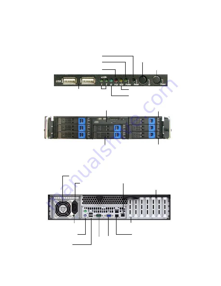
1.5.1 System Front View

1.5.2 System Rear View

Note:

 The above shows a single power supply setup (B5397T26W8H). A redundant 

power supply setup (B5397T26W6HR) is also available.  In both cases, the out-
put voltage is the same. 

Reset switch

USB ports

Warning LED

HDD activity LED

LAN LEDs

Hard Drive Bay x 8

DVD-ROM drive

HDD Tray
Activity LEDs

Power switch

Power LED

HDD Tray 
Power LEDs

ID switch

ID LED

Power Supply 
Socket

Serial 
Port

VGA
Port

Power Supply Fan

2 USB Ports

PS/2 Mouse and 
Keyboard Ports

LAN1 (top)
LAN2 (bottom) 

Low Profile
PCI-E Slots

LAN Port (IPMI)

Power Supply LED

ID LED

Содержание Tank TA26 B5397

Страница 1: ...Tank TA26 B5397 Service Engineer s Manual...

Страница 2: ......

Страница 3: ...ns at any time without notice In no event will TYAN be held liable for any direct or indirect incidental or consequential damage loss of use loss of data or other malady resulting from errors or inacc...

Страница 4: ...ent into an outlet on a circuit different from that of the receiver Consult the dealer on an experienced radio television technician for help Notice for Canada This apparatus complies with the Class B...

Страница 5: ...and provides block diagrams of the system Chapter 2 Covers procedures on installing the CPU mem ory modules PCI E card hard drives and floppy drive Chapter 3 Covers removal and replacement procedures...

Страница 6: ...his pin If your outlet does not support this kind of plug contact your electrician to replace your obsolete outlet Do not place anything on the power cord Place the power cord where it will not be in...

Страница 7: ...0 2 Work Area 13 2 0 3 Tools 13 2 0 4 Precautions 14 2 1 Installing Motherboard Components 15 2 1 1 Removing the Chassis Cover 15 2 1 2 Installing the CPU 17 2 1 3 Installing the Memory 20 2 1 4 Inst...

Страница 8: ...r Pin Definitions 47 3 7 Replacing the Backplane 48 3 7 1 M1220 SAS SATA Backplane Features 50 3 7 2 M1220 SAS SATA Backplane Connector Pin Definitions 52 3 8 Replacing the System Fan 56 3 9 Replacing...

Страница 9: ...y design The Tank TA26 B5397 not only empowers your company in today s demanding IT environment but also offers a smooth path for future application usage B5397 TYAN is also proud to deliver the Tank...

Страница 10: ...Console Redirect PXE via Ethernet USB device boot PnP DMI 2 0 WfM 2 0 Power Management User configuration of H W monitoring Auto configuration of hard disk types Multiple boot options 48 bit LBA suppo...

Страница 11: ...1 8 port SAS backplane supporting up to 8 SAS HDDs or SATA HDDs Networking One 1 Intel Gilgal 82563EB PHY Direct link to ESB6321 Two gigabit LAN ports Two front panel LED pin headers Power Supply EPS...

Страница 12: ...aged 1 4 1 Box Contents Component Description Industry standard 2U chassis 8 hot swap HDD bays TYAN Tempest i5400PW S5397 motherboard pre installed Slim DVD ROM drive pre installed LED and USB control...

Страница 13: ...r or browse to TYAN s Web site for service http www tyan com The Web site also provides information on other TYAN prod ucts plus FAQs compatibility lists BIOS settings and more 1 x TYAN Driver CD Powe...

Страница 14: ...6 Chapter 1 Overview Screw Pack Sliding Rail FDD Rails FDD Power Cable TYAN Logo...

Страница 15: ...6W6HR is also available In both cases the out put voltage is the same Reset switch USB ports Warning LED HDD activity LED LAN LEDs Hard Drive Bay x 8 DVD ROM drive HDD Tray Activity LEDs Power switch...

Страница 16: ...Blinking OFF HDD ready HDD access activity HDD not ready SATA HDD Green OFF Blinking OFF HDD access activity No disk activity LED Color State Description LAN Linkage Activity Left Side Green Green OF...

Страница 17: ...Chapter 1 Overview 9 1 5 4 Motherboard Layout...

Страница 18: ...der for Barebone J38 TYAN LCM Header for Barebone J41 USB Front Panel Header P1 Audio Jack Header J2 Aux Power Header for TYAN Riser Card M2061 JP1 Clear CMOS Jumper Close 1 2 Default Close 2 3 Clear...

Страница 19: ...Chapter 1 Overview 11 1 5 6 System Block Diagram...

Страница 20: ...Connector 3 Power Supply 4 Fan Duct 5 SAS SATA Backplane 6 LED Control Board Cable 7 Eight 8 SAS SATA HDD trays 8 DVD ROM Cable 9 System Fans Right to Left FAN1 FAN2 FAN3 10 Low Profile PCI E Slots 11...

Страница 21: ...s Use containers to keep small components separated Putting all small components in separate containers prevents them from becoming lost Adequate lighting and proper tools can prevent you from acciden...

Страница 22: ...of any other grounded appliance Avoid touching motherboard components IC chips connectors memory modules and leads The motherboard is pre installed in the system When removing the motherboard always p...

Страница 23: ...tall components on to the motherboard including CPU memory modules and PCI E card 2 1 1 Removing the Chassis Cover Follow these instructions to remove the Tank TA26 B5397 chassis cover 1 Turn the scre...

Страница 24: ...16 Chapter 2 Setting Up 3 Unscrew the fan duct...

Страница 25: ...Chapter 2 Setting Up 17 2 1 2 Installing the CPU Follow these instructions to install the CPU 1 Remove the cover on the CPU socket 2 Lift up the CPU lever to unlock the socket...

Страница 26: ...Setting Up 3 Open the socket in the direction as illustrated 4 Place the CPU in the CPU socket ensuring that pin 1 is located as shown below 5 Close the cover and press the CPU socket lever down to se...

Страница 27: ...Chapter 2 Setting Up 19 6 Place theheatsink on top of the CPU and secure with four screws as shown below...

Страница 28: ...ow these instructions to install the memory modules on the motherboard 1 Locate the memory slots on the motherboard 2 Press the memory slot locking levers in the direction of the arrows as shown below...

Страница 29: ...pter 2 Setting Up 21 4 When inserted properly the memory slot locking levers lock automaticaly onto the indentations at the ends of the module 5 Repeat these steps when installing a second memory modu...

Страница 30: ...22 Chapter 2 Setting Up The following chart outlines the suggested rules for populating memory...

Страница 31: ...for PCI E card installation 1 Locate the PCI E card slots on the motherboard See System Internal View on page 14 for the PCI E slot locations 2 Unscrew the bracket from the slot you want to use 3 Lift...

Страница 32: ...7 supports up to eight serial SAS SATA hard drives Follow these instructions to install a hard drive 1 Press the locking lever latch in the direction shown by the arrow below The latch will pop open 2...

Страница 33: ...apter 2 Setting Up 25 4 Remove the base 5 Place a hard drive into the drive tray 6 Screw the hard drive in place using 4 HDD screws 7 Reinsert the tray into the bay and press the locking lever to secu...

Страница 34: ...ructions to install a floppy disk drive in the TA26 B5397 1 Remove the top left hand drive tray from the TA26 B5397 as shown Note The top left hand drive bay is the only bay that can accommodate a flo...

Страница 35: ...catch mechanism on the right hand rail when looking at the floppy disk drive from the front 3 Plug the FDD power and data cables into the ports on the back of the floppy disk drive 4 Thread the cable...

Страница 36: ...power cable to the connec tor J37 on the backplane 6 Connect the other end of the supplied FDD cable to the FDD slot on the motherboard Note To release the floppy disk drive from the drive bay you wi...

Страница 37: ...Installing the Server in a Rack Follow these instructions to mount the TA26 B5397 into an industry standard 19 rack NOTE Before mounting the Tank TA26 B5397 in a rack ensure that all internal compone...

Страница 38: ...the Inner Rails to the Unit 7 Screw the handles to each side of TA26 B5397 as shown using two 2 M4L6 S10C screws A from the supplied screws kit 8 Attach the inner rails both sides of the unit using n...

Страница 39: ...ing Outer Rails to the Rack 1 Adjust the outer rail to match the length of the unit 2 Secure the outer rail to the rack using 2 brackets and M6 screws B for each side Secure the mounting brackets from...

Страница 40: ...er 2 Setting Up Rackmounting the Server 1 Draw out the middle rail to the latch position 2 Lift the unit and then insert the inner slide rails into the middle rails 3 Push the unit in and press the la...

Страница 41: ...h the whole system into the rack 5 Secure the mounting handles of the unit to the rack Note To avoid injury it is strongly recommended that two people lift the TA26 B5397 into the place while a third...

Страница 42: ...34 Chapter 2 Setting Up NOTE...

Страница 43: ...e malfunc tions Use containers to keep small components separated Putting all small components in separate containers keeps them from becoming lost Adequate lighting and proper tools can prevent you f...

Страница 44: ...tal body of any other grounded appli ance Avoid touching motherboard components IC chips connectors memory modules and leads The motherboard is pre installed in the system When removing the motherboar...

Страница 45: ...art outlines the disassembly procedure Note The Tank TA26 B5397 should be always powered off before disassembly Rear Components Chassis top cover Mainboard DIMMs CPU heatsink assembly PCI E card Mainb...

Страница 46: ...he Cover Before replacing any parts you must remove the chassis cover Follow these instructions to remove the cover of the Tank TA26 B5397 chassis cover 1 Turn the screw on the back side Then slide th...

Страница 47: ...Chapter 3 Replacing Pre Installed Components 39 3 Unscrew the fan duct...

Страница 48: ...he motherboard 3 4 1 Disconnecting All Motherboard Cables Before replacing the motherboard or certain components remove cables connected to the motherboard Follow these instructions to remove all moth...

Страница 49: ...he Motherboard After removing all of the aforementioned cables follow these instructions to remove the motherboard from the chassis 1 Remove ten mainboard screws and one fan duct screw securing the mo...

Страница 50: ...Heatsink mounting plate stand offs They are the stand offs to which you mount the CPU heatsink 2 Take out the black mylar from the chassis 3 Unscrew the eight chassis mounting stand offs to remove th...

Страница 51: ...cing the Slim DVD ROM Follow these instructions to replace the DVD ROM 1 Remove the FFC cable from the rear of the DVD ROM drive 2 Press the tab in the direction shown to release the DVD ROM drive 3 P...

Страница 52: ...Components 4 Remove the two screws that secure DVD ROM drive to the backplane 5 Replace the DVD ROM drive 6 Secure the DVD ROM to the backplane using two screws Then replace the unit into the drive ba...

Страница 53: ...ED Control Board Follow these instructions to replace the LED control board 1 Remove the screw securing the LED control board unit to the chassis 2 Remove the connector cables from the backplane 3 Sli...

Страница 54: ...LED control board and USB adapter board 5 Remove the five screws securing the LED control board and USB adapter board to the bracket 6 Release the LED control board and USB adapter board from bracket...

Страница 55: ...D 6 LAN2 LED 7 Reserved 8 Reserved 9 Reserved 10 Reserved 11 ID LED 12 ID LED 13 W LED 14 W LED 15 Local HDD led 16 Local HDD led 17 System power led 18 System power led 19 System reset switch 20 Syst...

Страница 56: ...of cables connected to the backplane includ ing fan cables DVD ROM cables LED control board cable fan control cable TYFP cable USB cables front panel LED cables power cables and SAS SATA cables SAS SA...

Страница 57: ...o release the backplane 3 Turn the locking keys at the base of the backplane as shown 4 Pull out the backplane 5 Place a new backplane in position and secure in place with the ten screws and locking k...

Страница 58: ...1 M1220 SAS SATA Backplane Features Front View J35 2x7pin LED J13 29pin SAS J14 29pin SAS J15 29pin SAS J34 2x5pin LED J11 29pin SAS J12 29pin SAS J7 40pin cd rom B J33 2x12pin LED B J5 2x5pin USB J36...

Страница 59: ...ear View J1 J2 J3 big 4pin FAN1 4pin J6 TO CD ROM FAN2 4pin J37 small 4pin FAN3 4pin J32 LED B J4 USB OUT J25 J27 J29 J31 7pin secondary J24 J26 J28 J30 7pin primary J38 2x7pin tach and PWM J17 J19 J2...

Страница 60: ...LAN2 LED link active 6 LAN2 LED link active 7 Reserved 8 Reserved 9 Reserved 10 Reserved 11 ID LED 12 ID LED 13 W LED 14 W LED 15 M B HDD LED 16 M B HDD LED 17 M B power LED 18 M B power LED 19 M B re...

Страница 61: ...W circuit design only It might be different from the system fan name FAN1 FAN2 FAN3 4 pin Fan connector J1 J2 and J3 power big 4 pin connector 25 DIOR 26 VCC 27 IORDY 28 CSEL 29 DMACK 30 VCC 31 INTRQ...

Страница 62: ...D LED pin out 1 USB1 power 2 USB2 power 3 USB1 DATA 4 USB2 DATA 5 USB1 DATA 6 USB2 DATA 7 USB1 GND 8 USB2 GND 9 Key pin 10 None 1 5V 2 GND 3 GND 4 12V 1 PLED1 2 GND 3 ALED1 4 ALED1 5 PLED2 6 GND 7 ALE...

Страница 63: ...AN tach and PWM pin out 1 PLED6 2 GND 3 ALED6 4 ALED6 5 PLED7 6 GND 7 ALED7 8 ALED7 9 PLED8 10 GND 11 ALED8 12 ALED8 13 None 14 Key 1 FAN1 tach 2 Reserved 3 FAN2 tach 4 Reserved 5 FAN3 tach 6 Reserved...

Страница 64: ...Follow these instructions to replace the cooling fans in your TA26 B5397 system 1 Locate the fan connector on the backplane and unplug the fan cable as shown below 2 Take the fan away from the chassi...

Страница 65: ...s to replace the power supply in your TA26 B5397 system 1 Remove the chassis cover See Removing the Cover on page 38 for more details 2 Detach the power cables from the motherboard and backplane See D...

Страница 66: ...Components 4 Remove the two screws attaching the power supply to the chassis interior and lift out the unit 5 Lift the power supply free from the chassis 6 Replace a new power supply into the chassis...

Страница 67: ...wer supply is fitted either of the two units can be hot swapped Follow these instructions to replace a single power unit with a redundant power supply unit Note Before proceeding remove the new redund...

Страница 68: ...0 Chapter 3 Replacing Pre Installed Components 2 Lift the power supply free from the chassis 3 Lift the bracket free from the chassis 4 Screw the bracket to the rear of the redundant power supply cage...

Страница 69: ...Chapter 3 Replacing Pre Installed Components 61 5 Insert the redundant power supply cage into the chassis 6 Screw the cage to the chassis exterior 7 Screw the cage to the chassis interior...

Страница 70: ...62 Chapter 3 Replacing Pre Installed Components 8 Insert the new power supply unit and secure by turning the locking screw...

Страница 71: ...Chapter 3 Replacing Pre Installed Components 63 9 Reattach all power supply connector cables to the moth erboard and backplane...

Страница 72: ...64 Chapter 3 Replacing Pre Installed Components NOTE...

Страница 73: ...w of S5397 BIOS refer to the motherboard manual Table of Differences S5397 Mainboard B5397 Barebone Advanced Hardware Monitor Fan Speed Moni toring CPU0 CPU1 Rear Chass FAN Front Chass FAN PCI FAN Sys...

Страница 74: ...A26 B5397 Model M1220 SAS SATA Backplane Connects to Motherboard J16 mini SAS0 3 J18 J20 J22 J24 mini SAS4 7 J26 J28 J30 Table 2 System Fan to Backplane System Fan Connects to M1220 SAS SATA Backplane...

Страница 75: ...W1 4 pin connector PC 4 pin power cable PW3 4 pin connector Table 4 Power Supply to Backplane Power Supply Connects to M1220 SAS SATA Backplane PD 4 pin power cable J1 4 pin connector PE 4 pin power c...

Страница 76: ...les to Backplane M1220 SAS SATA Backplane Front side Connects to TA26 B5397 System J34 2x5pin LED System Internal LED Cables J35 2x7pin LED J36 2x7pin LED Table 8 DVD ROM Related Cable M1220 SAS SATA...

Страница 77: ...3295 2 M3296 SMDC card into your TA26 B5397 sys tem 1 Locate the SO DIMM TARO card socket on the mother board See System Internal View on page 14 for the SO DIMM socket location 2 Press the SO DIMM so...

Страница 78: ...70 Appendix 4 When inserted properly the SO DIMM socket locking levers lock automaticaly onto the indentations at the ends of the TARO card...

Страница 79: ...Tray CHDT 0030 340731500035 8 Removable 3 5 HDD Tray CPSU 0160 471172400087 1 700W Single Power Supply CPSU 0350 471015200193 2 700W 1 1 redundant PSU module CPSU 0351 471015200197 1 700W 1 1 redunda...

Страница 80: ...U Backplane Kit CPCA 0270 1 Front Control Board M1220 1 SAS SATA 8 port Backplane Dual Host CPCA 0080 1 Front Control Board CPCA 0250 1 Slim DVD ROM Adapter Board M3295 2 1 SMDC Card M3296 1 SMDC Card...

Страница 81: ...00280 1 A C Power Cord 2440mm US Type CCBL 0300 332810000281 1 A C Power Cord 1800mm Germany Type CCBL 067C 422772500001 1 Mini SAS Cable 36P to 4X7P 400mm CCBL 067D 422772500002 1 Mini SAS Cable 36P...

Страница 82: ...d 130mm CCBL 0120 422732600018 1 LED Board Cable 253mm CCBL 0433 422740900009 1 DVD ROM Cable 395mm CCBL 0144 422763200004 1 Chassis Intrusion Cable 800mm CCBL 0841 422763200002 1 FAN Cable 380mm CCBL...

Страница 83: ...pectations TYAN s website www tyan com provides easy to access resources such as in depth Linux Online Support sections with downloadable Linux drivers and comprehensive compatibility reports for chas...

Страница 84: ...and does not cover damages incurred during shipping or failure due to the alteration mis use abuse or improper maintenance of products NOTE A receipt or copy of your invoice marked with the date of p...

Отзывы: