


S2420 Tomcat i810ef
23
Pin 1 on the CPU is denoted by a small dot on one of the corners and Pin 1 on
the ZIF socket is denoted by an angled corner (see
Figure 2-6
on previous
page). Never force a CPU into a socket. Forcing a CPU to seat will bend the
pins on the CPU and possibly damage the motherboard. Push down lightly on
the CPU, and lower the arm on the ZIF socket to secure the CPU. A squeaking
noise is normal as the arm lowers. After the CPU is securely seated, install the
appropriate cooling device. Tyan strongly recommends a heatsink/fan combi-
nation. Consult with your case manufacturer for other cooling options.
Locate
the cooling fan connector (e.g. CPU Fan) on the motherboard. Plug the CPUs
cooling fan cable into the cooling fan connector on the board. There will be a
plastic clip assembly similar to that of the ATX power connector that will force
you to connect the fan cable correctly (see
Figure 2-7
on the previous page).
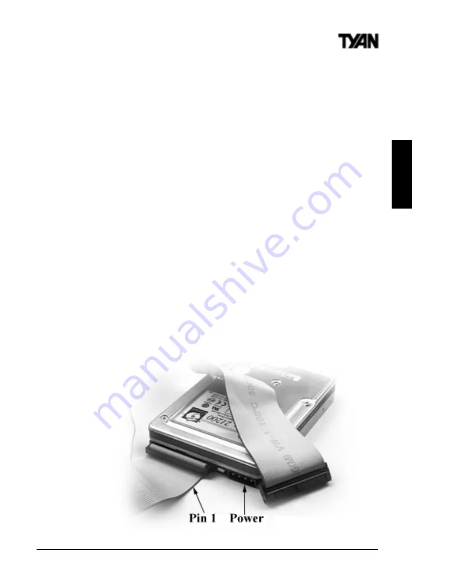
Connecting IDE and Floppy Drives
The colored stripe on a ribbon cable should face toward the ATX Power
Connector on the motherboard. In
Figure 2-8
below, you can see how the IDE
cables should look when they are connected to your hard drive. Notice how
Pin 1 (denoted by a red stripe) is connected so that it is next to the power
connector of the drive. The primary IDE connector is black; the secondary IDE
connector is white. In most cases, this is the proper way of connecting your
IDE cable to the hard drive.
Figure 2-9
on the next page shows the IDE cable
properly connected to the motherboard. Contact your hard disk drive manu-
facturer or documentation for more information.
Figure 2-8
INST
A
LL


