background image


http://www.tyan.com


35

3. 

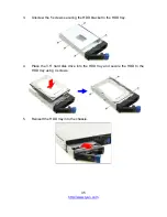
Unscrew the 5 screws securing the HDD bracket to the HDD tray. 


4. 

Place the 3.5” hard disk drive into the HDD tray and secure the HDD to the 
HDD tray using 4 screws.   


5. 

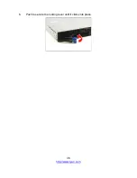
Reinsert the HDD tray into the chassis.   


Содержание GT24B-B5542

Страница 1: ...GT24B B5542 Service Engineer s Manual...

Страница 2: ...ity or warranties relating to fitness for a particular purpose or merchantability MITAC retains the right to make changes to produce descriptions and or specifications at any time without notice In no...

Страница 3: ...n radiate radio frequency energy and if not installed and used in accordance with the instruction manual may cause harmful interference to radio communications Operation of this equipment in a residen...

Страница 4: ...ter provides an introduction to the TYAN GT24B B5542 barebones and standard parts list describes the external components gives an overview of the product from different angles Chapter 2 Setting Up Thi...

Страница 5: ...the purpose of this pin If your outlet does not support this kind of plug contact your electrician to replace your obsolete outlet Do not place anything on the power cord Place the power cord where it...

Страница 6: ...The potential for injury exists if cautions are not observed Consult equipment documentation for specific details Caution Slide mounted equipment is not to be used as a shelf or a work space Warning...

Страница 7: ...nees bent Equipment Racks To avoid injury or damage to the equipment Observe local occupational health and safety requirements and guidelines for manual materials handling Do not attempt to move a rac...

Страница 8: ...equipment on top of the unit It will cause restricted airflow and might cause damage to the equipment Make sure the product is properly matted with the rails Products that are improperly matted with...

Страница 9: ...battery in fire or water Do not expose the battery to temperatures higher than 60 C 140 F The system battery is not replaceable If the battery is replaced by an incorrect type there is danger of explo...

Страница 10: ...all watches rings or loose jewelry when working before removing covers and touching internal components Do not use conductive tools that could bridge live parts Use gloves when you remove or replace...

Страница 11: ...3 Installing the PCI E Card 29 2 1 4 Installing the Memory 31 2 1 5 Installing Hard Drives 34 2 2 Rack Mounting 39 2 2 1 Installing the Server in a Rack 39 Chapter 3 Replacing Pre Installed Components...

Страница 12: ...3 8 1 Power Distribution Board Features 60 3 8 2 Power Distribution Board Pin Definitions 61 3 9 Replacing the Power Supply 63 Appendix I Cable Connection Tables 65 Appendix II Fan and Temp Sensors 6...

Страница 13: ...mory design providing a rich feature set and incredible performance and lightning fast PCI E bus implementation The GT24B B5542 not only empowers your company in nowadays IT demand but also offers a s...

Страница 14: ...rive Bay Type Q ty 2 5 3 5 Hot Swap 4 HDD backplane support SATA 6Gb s SAS 12Gb s Supported HDD Interface 4 SATA 6Gb s System Cooling Configuration FAN 3 4cm fans Power Supply Type RPSU Input Range AC...

Страница 15: ...ype D Sub 15 pin Resolution Up to 1920x1200 Chipset Aspeed AST2400 I O Ports USB 6 USB 3 0 ports 4 at rear 2 at front 1 USB 2 0 port 1 type A onboard COM 1 DB 9 port COM1 1 header COM2 VGA 1 D Sub 15...

Страница 16: ...MBIOS 3 0 PnP Wake on LAN ACPI sleeping states S3 S4 S5 Operating System OS supported list Please refer to our Intel OS supported list Regulation FCC DoC Class A CE DoC Yes Operating Environment Opera...

Страница 17: ...damaged contact your retailer or browse to TYAN s website for service http www tyan com GT24B B5542 Box Content 1 1U chassis 1 S5542 pre installed 3 Fan modules 2 Power supply modules 1 Hard Drive Bac...

Страница 18: ...g views show you the product 1 5 1 System Front View M1713G24 FPB Front Panel Board 1 USB3 0 Ports 2 ID Button 3 NMI Button 4 Reset Button 5 ID LED 6 HDD LED 7 Warning LED 8 LAN1 LED 9 LAN2 LED 10 LAN...

Страница 19: ...een solid on Access Blinking Warning LED Amber System Normal Off System Warning Amber solid on LAN1 LED Green Access Blinking Link Solid on LAN2 LED Green Access Blinking Link Solid on LAN3 LED N A No...

Страница 20: ...r Description ID LED On Blue System identified Off Off System not identified NOTE Press the ID button when the system AC Alternating Current is on then the ID LED will light blue if the system is iden...

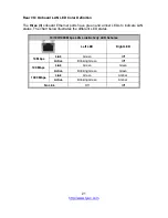
Страница 21: ...LEDs to indicate LAN status The chart below illustrates the different LED states 10 100 1000 Mbps LAN Link Activity LED Scheme Left LED Right LED 10 Mbps Link Green Off Active Blinking Green Off 100 M...

Страница 22: ...5 3 System Top View 1 4 hot swap HDD trays 1 M1713G24 FPB Front Panel Board 2 1 M1277G24 BP12 4 HDD Backplane Board 3 3 system fans 4 M7016 B7066 Power Distribution Board 5 1 1 RPSU 6 Riser Card Brack...

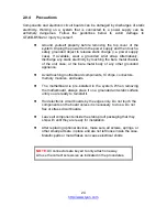
Страница 23: ...ts separated Putting all small components in separate containers prevents them from becoming lost Adequate lighting and proper tools can prevent you from accidentally damaging the internal components...

Страница 24: ...any other grounded appliance Avoid touching motherboard components IC chips connectors memory modules and leads The motherboard is pre installed in the system When removing the motherboard always plac...

Страница 25: ...ding CPUs memory modules and add on cards 2 1 1 Removing the Chassis Cover Follow these instructions to remove GT24B B5542 chassis cover 1 Remove the screw on the right side and unscrew the rear top c...

Страница 26: ...CPU and Heatsink Follow the steps below on installing CPUs and CPU heatsinks 1 Take off the air duct 2 Locate the CPU socket 3 Pull the lever slightly away from the socket and then push it to a fully...

Страница 27: ...Push the CPU socket cover to a fully open position 5 Place the CPU into the socket and make sure that the gold arrow is located in the right direction 6 Close the CPU socket cover and press the lever...

Страница 28: ...28 http www tyan com 7 Position the heatsink on top of the CPU and secure it with 4 screws 8 Put the air duct back in place...

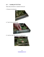
Страница 29: ...p www tyan com 2 1 3 Installing the PCI E Card Follow these instructions to install the PCI E card 1 Release the locking tab 2 Take off the dummy bracket 3 Insert the PCI E card into the riser card br...

Страница 30: ...30 http www tyan com 4 Close the locking tab...

Страница 31: ...emory slot locking levers in the direction of the arrows as shown in the following illustration 2 Align the memory module with the slot When inserted properly the memory slot locking levers lock autom...

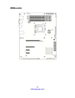
Страница 32: ...32 http www tyan com DIMM Location...

Страница 33: ...2 Use paired memory installation for max performance 3 Populate the same DIMM type in each channel specifically Use the same DIMM size Use the same of ranks per DIMM 4 Dual rank DIMMs are recommended...

Страница 34: ...2 5 hard drives Installing 3 5 Hard Drives Follow these instructions to install a 3 5 HDD Warning Always install the hard disk drive to the chassis after the chassis has been secured on the rack 1 Pre...

Страница 35: ...com 35 3 Unscrew the 5 screws securing the HDD bracket to the HDD tray 4 Place the 3 5 hard disk drive into the HDD tray and secure the HDD to the HDD tray using 4 screws 5 Reinsert the HDD tray into...

Страница 36: ...36 http www tyan com 6 Push to secure the locking lever until it clicks into place...

Страница 37: ...ves Follow these instructions to install a 2 5 HDD Warning Always install the hard disk drive to the chassis after the chassis has been secured on the rack 1 Press the locking lever latch and pull the...

Страница 38: ...tyan com 3 Turn the HDD tray over and place the 2 5 HDD on its bay Secure the HDD to the tray using 4 screws 4 Reinsert the HDD tray into the chassis 5 Push to secure the locking lever until it clicks...

Страница 39: ...ck x 1 2 2 1 Installing the Server in a Rack Follow these instructions to mount the TYAN GT24B B5542 into an industry standard 19 rack NOTE Before mounting the TYAN GT24B B5542 in a rack ensure that a...

Страница 40: ...shown using four screws from the supplied mounting ears screw pack 2 Draw out the inner rail from the rail assembly When the rail comes to a stop pull the tab to release the latch and completely draw...

Страница 41: ...41 http www tyan com 4 Secure the inner sliding rail to the server using one M4 x 4L screw B 5 Repeat steps 2 to 4 to secure the sliding rail to the other side of the server...

Страница 42: ...o the Unit Secure the outer rails to the rack using four M5 screws and four washers A on each side Rack Mounting the Server 1 Draw out the middle rail to the latch position 2 Lift the unit and then in...

Страница 43: ...43 http www tyan com 3 When the inner rails come to a stop pull the tab to release the latch and push the whole system in 4 Secure the mounting ears of the unit to the rack using two M5 x 20L screws C...

Страница 44: ...44 http www tyan com NOTE...

Страница 45: ...ow to replace the pre installed components including the Motherboard M1713 G24 FPB Front Panel Board M1277G24 BP12 4 HDD Backplane M7016 B7066 Power Distribution board M2091 Riser card System fan and...

Страница 46: ...sis cover first Follow Chapter 2 1 1 to remove the cover of the GT24B B5542 3 4 Replacing Motherboard Components Follow these instructions to replace motherboard components including the motherboard 3...

Страница 47: ...er Card Follow these instructions to replace the M2091 riser card 1 Unscrew to lift up the riser card bracket 2 Unscrew the M2091 riser card to replace with a new one 3 Follow the steps described earl...

Страница 48: ...of the aforementioned cables follow the instructions below to remove the motherboard from the chassis 1 Remove the air duct processor and heatsink if installed 2 Remove nine screws securing the mother...

Страница 49: ...the Front Panel Board Follow these instructions to replace the M1713G24 FPB Front Panel Board 1 Remove the two screws securing the front panel board to the chassis 2 Push the front panel board out an...

Страница 50: ...three screws securing the front panel board to the bracket 4 Lift the front panel board free from the bracket After replacing the front panel board insert the FPB bracket into the chassis following th...

Страница 51: ...Panel Board in details Form Factor 97x45 2 mm 4 layer PCB Specifications 1 10x2 pin USB3 0 Header connected to MB 1 15x2 pin Header connected to MB 2 USB3 0 Connector LEDs 1 Green Blue LED for LAN1 a...

Страница 52: ...6 16 GND GND 7 17 FP_USB3_RX_P1 USB0 8 18 FP_USB3_RX_N1 USB0 9 19 VCC_USB NC 10 20 Key J3 Front Panel Board Connector Definition Pin Pin Definition PW_LED 1 16 ICH_SMBDAT VCC 2 17 GND Key 3 18 ICH_SM...

Страница 53: ...tp www tyan com 3 6 Replacing the System Fan Follow these instructions to replace the cooling fans in your system 1 Unplug the fan cables connected to the HDD backplane 2 Lift the fans up from the cha...

Страница 54: ...rection as the arrow shown to release the fan from the plastic holder Step A 4 Remove the plastic holder to replace a new fan Step B 5 After replacing with new fans insert the fan modules into the cha...

Страница 55: ...ach the HDD backplane please remove all the HDD trays with HDDs otherwise the HDD backplane will be damage when strains at the disassembly 1 Disconnect all cables connected to the M1277G24 BP 12 4 HDD...

Страница 56: ...56 http www tyan com 2 The HDD BP Board bracket show as the following image 3 Unscrew the HDD BP Board and remove the BP mylar 4 Take the HDD BP Board and the iron bracket apart...

Страница 57: ...View Form Factor Dimension 422 4 29 8mm Integrated I O 4 SAS SATA 6G 4 SATA SAS HD connectors 2 1x4 pin power connector 1 4 pin power connector for reserve 1 2x5 pin JTAG connector TBD 1 2x5 pin SGPI...

Страница 58: ...KEY PWM2 13 14 PWM1 TACH11 15 16 SDA TACH12 17 18 SCL VCC 19 20 PWM3 FAN1 6 FAN2 7 FAN3 8 FAN4 9 FAN5 10 FAN11 12 8 pin Fan Header Signal Pin Pin Signal PWM1 1 2 VCC1 TACK1 3 4 GND1 GND2 5 6 TACK2 VC...

Страница 59: ...M7016 B7066 PDB in your system 1 Press the latch to pull the two power supplies out 2 Disconnect all cables connected to the power distribution board 3 Unscrew to take off the power distribution boar...

Страница 60: ...60 http www tyan com 3 8 1 Power Distribution Board Features PWR1 ATX 2 ATX 1 2x2 Pin PWR CONN 1x4 Pin PWR CONN 1x4 Pin PWR CONN PSMI CONN...

Страница 61: ...V1 5 6 12V1 12V3a 7 8 12V3a PW1 24 pin Power Connector Definition Pin Pin Definition 3 3V 1 2 3 3V GND 3 4 5V GND 5 6 5V GND 7 8 Power Good 5VSB 9 10 12V 12V 11 12 3 3V 3 3V 13 14 12V GND 15 16 PS_ON...

Страница 62: ...62 http www tyan com J4 PSMI Connector Pin 1 2 3 4 5 Definition SMBUS_CLK SMBUS_DATA NC NC GND...

Страница 63: ...er Supply Follow these instructions to replace the power supply module in your system 1 Press the latch to pull the power supply out 2 After replacing a new power supply press and hold the latch to pu...

Страница 64: ...64 http www tyan com NOTE...

Страница 65: ...n2 FAN3 Fan3 FAN4 2 Mini SAS Cable FAN Cable SGPIO Cable M1277 SATA SAS Backplane BP Board to S5542 MB Cable M1277 Connect to S5542 Mini SAS to 4port SATA Cable SATA0 SATA3 J46 J45 J44 J43 SGPIO Cable...

Страница 66: ...o S5542 2x12P CABLE PWR1 PW1 2x4P CABLE ATX1 PW2 PSMI CABLE PSMI PSMI M7016 B7066 PDB to M1277 Backplane BP Board M7016 B7066 Connect to M1277 B4P CABLE 1x4P PWR PW1 B4P CABLE 1x4P PWR PW2 5 Intrusion...

Страница 67: ...of BIOS Temp sensor name explanation is also included for readers reference NOTE The red mark indicates the sensor Fan and Temp Sensor Location 1 Fan Sensor It is located in the third pin of the fan c...

Страница 68: ...68 http www tyan com BIOS Temp Sensor Name Explanation...

Страница 69: ...tem Air Inlet Area MB_Air_Inlet Temperature of MB Air Inlet Area Sys_Air_Outlet Temperature of System Air Outlet Area PCH_Temp Temperature of the PCH CPU_DIMM_A0 Temperature of CPU DIMM A0 Slot CPU_DI...

Страница 70: ...70 http www tyan com NOTE...

Страница 71: ...C Power Cord L 1800mm US type CCBL 0300 332810000281 A C Power Cord L 1830mm EU type Power Supply FRU PS 0050 471100000105 3Y YM 2451GA01R 450W FAN FRU TS 0100 336210000046 22000 RPM 40 40 28MM Rack...

Страница 72: ...72 http www tyan com NOTE...

Страница 73: ...s such as in depth Linux Online Support sections with downloadable Linux drivers and comprehensive compatibility reports for chassis memory and much more With all these convenient resources just a few...

Страница 74: ...oper maintenance of products Note A receipt or copy of your invoice marked with the date of purchase is required before any warranty service can be rendered You may obtain service by calling the manuf...

Отзывы: