background image

VERA RF600i Assembly Instructions

24

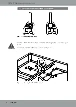
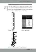
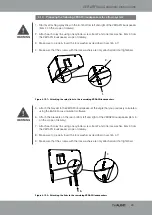
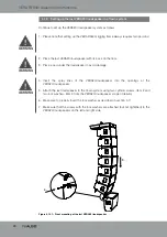
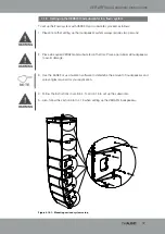
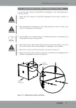
  4.11    Setting up the following VERA20i loudspeakers in a flown system

Continue to set up the VERA20i loudspeaker system for rigging as follows:

1.  Please note that setting up the VERA RF600i rigging frame always requires two persons!

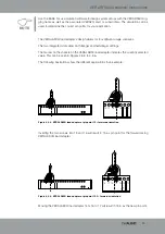
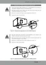
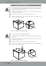
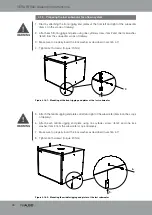
2.  Place all remaining VERA20i loudspeakers with their backs on the floor. Place pads under 

the loudspeakers to avoid damage.

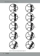
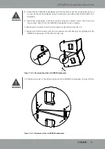
3.  Insert the splay links into the openings at the VERA20i loudspeaker.

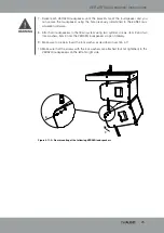
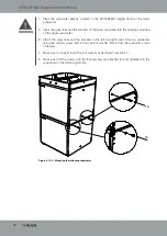
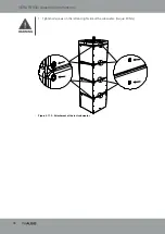
4.  Attach all loudspeakers to the flown system using two cylinder screws, item 2 and two 

lock washers, item 3 from the VERA20i loudspeaker scope of delivery.

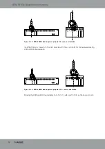
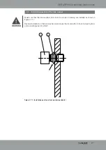
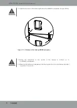
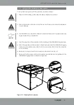
5.  Make sure to properly insert the lock washer as described in section 4.7!

6.  Make sure that the screws with the lock washers are attached (but not tightened) to the 

VERA20i loudspeakers on the left and right side.

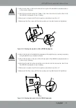
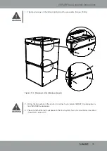
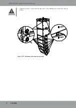
Figure 4.11.1 – Front mounting of the following VERA20i loudspeakers


3.

4.

WARNING

WARNING

WARNING

Содержание VERARF600i

Страница 1: ...Assembly Instructions VERARF600i...

Страница 2: ...here to the instructions contained in this assembly guide that are marked as follows This symbol in combination with the signal word Caution identifies a potentially hazardous situation Failure to com...

Страница 3: ...ct to the best of our knowledge at the time of printing Quality warranties or assurance of suitability for a certain type of use based on the technical specifications dimensions and weights are not gr...

Страница 4: ...ERA20i loudspeaker in a flown system 20 4 10 Preparing the following VERA20i loudspeakers for a flown system 23 4 11 Setting up the following VERA20i loudspeakers in a flown system 24 4 12 Preparing t...

Страница 5: ...use the VERARF600i rigging frame Any other use shall be deemed improper and may result in damage or even injury Modifications or alterations to individual parts of the VERARF600i rigging frame and th...

Страница 6: ...er cables or other cables attached to the VERA20i and or subwoofers The respective national electrotechnical regulations apply All screw connections should be checked when the VERARF600i rigging frame...

Страница 7: ...VS 8 1 4301 7 pcs 4 Front rigging end plate powder coated surface 4 pcs 5 Middle rigging end plate powder coated surface 2 pcs 6 Load adapter with VERALA900i shackle 1 pc 7 M8x25 12 9 fitting screw 2...

Страница 8: ...to e g 24x VERA20i or 12xVERAS17i or 10x VERAS32i units Dimensions h x w x d 80 x 600 x 600mm 3 1 x 23 6 x 23 6 in Weight 16 7kg 36 lbs Surface Powder coated Please note that the loudspeakers VERAS17i...

Страница 9: ...by TWAUDiO for securing and mounting the rigging frame 4 2 Necessary tools for setting up the flown system Torque wrench Bit insert for torque wrench TX45 SW13 fork wrench Whenever you make changes to...

Страница 10: ...ter in flown systems Figure 4 3 1 VERALA900i load adapter Attach the VERALA900i load adapter to the VERARF600i rigging frame as shown in figure 4 3 2 Use items 7 8 and 9 from the scope of delivery see...

Страница 11: ...rations show the different applications in an example Use the EASE Focus simulation software to design system setups with the VERARF600i rig ging frame as well as the associated VERA20i and or subwoof...

Страница 12: ...the VERALA900i load adapter from 15 to 14 will result in 15 5 as the new pin point Figure 4 3 5 VERALA900i load adapter at pin point 16 reverse orientation Inserting the two screws into 15 and 16 wil...

Страница 13: ...nt example Attach a second separate safety component to the for safety wire points D and E This can be safety chains for example Figure 4 4 2 Secondary safety component example Please obtain about reg...

Страница 14: ...isassemble your system immediately when wind forces exceed 8bft 34 to 40kn 38 5 to 46mph Make sure that there are no persons in the close proximity of the flown system Make sure that your system will...

Страница 15: ...s position 4 of the scope of delivery 2 When setting up the flown system with VERA20i loudspeakers please refer to the detailed views for each individual angle setting as seen on the next page 0 0 3 0...

Страница 16: ...VERARF600i Assembly Instructions 16 Figure 4 6 4 Detail views of the angle settings from figure 4 6 3 0 0 3 0 8 1 5 2 4 3 5 4 9 6 8 9 1 12...

Страница 17: ...that the lock washers item 3 on the scope of delivery are installed as shown in figure 4 7 1 Reverse installation of the lock washer would cause the lock washer to have no biasing force and accordingl...

Страница 18: ...described in section 4 7 4 Make sure that the screws with the lock washers are only attached and not tightened Figure 4 8 2 Attaching the brackets to the first VERA20i loudspeaker 5 Turn the bracket a...

Страница 19: ...rs are only attached and not tightened Figure 4 8 4 Attaching the brackets to the first VERA20i loudspeaker 14 Attach the bracket to the VERA20i loudspeaker at the angle that you previously calculated...

Страница 20: ...rmine the amount of loudspeakers and splay angles required for your application To set up a flown system with the VERA20i loudspeakers proceed as follows 1 Please note that setting up the VERARF600i r...

Страница 21: ...asher item 2 from the VERA20i loudspeaker scope of delivery for attaching the brackets to the VERARF600i rigging frame 10 Make sure to properly insert the lock washer as described in section 4 7 11 Ma...

Страница 22: ...tions 22 Figure 4 9 3 Attachment of the first VERA20i loudspeaker at the VERARF600i rigging frame 12 Tighten all screws on the left and right side of the VERA20i loudspeaker and the VERARF600i rigging...

Страница 23: ...Make sure that the screws with the lock washers are only attached and not tightened Figure 4 10 2 Attaching the links to the remaining VERA20i loudspeakers 5 Attach the bracket to the VERA20i loudspea...

Страница 24: ...loudspeakers to avoid damage 3 Insert the splay links into the openings at the VERA20i loudspeaker 4 Attach all loudspeakers to the flown system using two cylinder screws item 2 and two lock washers i...

Страница 25: ...loudspeakers to the flown system using two cylinder screws item 2 and two lock washers item 3 from the VERA20i loudspeaker scope of delivery 9 Make sure to properly insert the lock washer as describe...

Страница 26: ...all screws on the left and right side of the VERA20i loudspeaker torque 20Nm 12 Follow the instructions in this section of the manual to connect up to 24 VERA20i loudspeakers 13 Please note that the...

Страница 27: ...0i loudspeaker scope of delivery 3 Make sure to properly insert the lock washer as described in section 4 7 4 Tighten both screws torque 20Nm Figure 4 12 2 Mounting the middle rigging end plates at th...

Страница 28: ...on the floor 3 Place a pad under the loudspeaker to avoid damage 4 Insert the splay links of the VERA20i loudspeaker into the openings at the VERA20i loudspeaker 5 Attach the last loudspeaker to the f...

Страница 29: ...e loudspeaker and you can secure the last loudspeaker using the hole previously determined in the EASE Focus simulation 9 Attach the loudspeaker to the flown system using two cylinder screws item 2 an...

Страница 30: ...em 3 from the subwoofer scope of delivery 3 Make sure to properly insert the lock washer as described in section 4 7 4 Make sure that the screws with the lock washers are attached but not tightened to...

Страница 31: ...ks of the subwoofer into the openings at the VERARF600i rigging frame 5 Attach the splay links and the brackets to the left and right side of the VERARF600i rigging frame using one cylinder screw item...

Страница 32: ...fer into the openings provided on the upper subwoofer 3 Attach the splay links and the brackets to the left and right side of the top subwoofer using one cylinder screw item 2 and one lock washer item...

Страница 33: ...ighten all screws on the left and right side of the subwoofer torque 20Nm 2 Follow the instructions in this section to connect up to twelve VERAS17i loudspeakers or ten VERAS32i loudspeakers 3 Please...

Страница 34: ...om the subwoofer scope of delivery 3 Make sure to properly insert the lock washer as described in section 4 7 4 Tighten both screws torque 20Nm WARNING Figure 4 16 2 Mounting the middle rigging end pl...

Страница 35: ...the floor Place a pad under the loudspeaker to avoid damage 3 Insert the splay links and the brackets of the subwoofer into the openings at the top of the subwoofer 4 Attach the last loudspeaker in t...

Страница 36: ...VERARF600i Assembly Instructions 36 Figure 4 17 2 Attachment of the last subwoofer WARNING 1 Tighten all screws on the left and right side of the subwoofer torque 20Nm...

Страница 37: ...o persons 2 Place all required VERA20i and subwoofer on the floor Place a pad under all loudspeakers to avoid damage WARNING NOTE 3 Use the EASE Focus simulation software to determine the amount of lo...

Страница 38: ...VERARF600i Assembly Instructions 38 Figure 4 18 2 Attachment of the mixed system setup WARNING 1 Tighten all screws on the left and right side of the VERA20i and subwoofer torque 20Nm...

Страница 39: ...loudspeaker to avoid damage 4 Attach the rear splay links and the brackets on the side using one cylinder screw item 2 and one lock washer item 3 from the VERAS17i loudspeaker scope of delivery 5 Make...

Страница 40: ...cardioid system using for the left and right side two cylinder screws item 2 and two lock washers item 3 from the VERAS17i loudspeaker scope of delivery 3 Make sure to properly insert the lock washer...

Страница 41: ...VERARF600i Assembly Instructions 41 WARNING 5 Tighten all screws on the left and right side of the VERAS17i loudspeaker torque 20Nm Figure 4 19 3 Attachment of the cardioid system setup...

Страница 42: ...sys tem setup with VERAS17i loudspeakers are available at TWAUDiO Figure 4 19 4 Attachment of an optional front grill WARNING 2 Follow the instructions in this section to connect up to twelve VERAS17i...

Страница 43: ...ARF600i rigging frame through the front and the middle rigging tracks Make sure that the load is never transferred from one rigging track to another rigging track through the speaker enclosure WARNING...

Страница 44: ...ng frame is not damaged during transport and storage Moisture may penetrate where steel surfaces are exposed by scratches and result in corro sion This is why the product should be transported in a sa...

Страница 45: ...n applies to the following components VERARF600i as well as all model variants based on these provided that they correspond to the original factory models and have not been technically modified in any...

Страница 46: ...VERARF600i Assembly Instructions 46 TWAUDiO GmbH Osterholzallee 140 71636 Ludwigsburg Germany Phone 49 0 71 41 48 89 89 0 Fax 49 0 71 41 48 89 89 99 E Mail info twaudio de WWW www twaudio de...

Отзывы: