


3
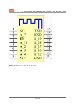
MODULE INTERFACES
Pin Number
Symbol
I/O Type
Function
10
A_12
I/O
GPIOA_12,
hardware PWM, IC
Pin 26
11
A_16
I/O
GPIOA_16,
UART_Log_TXD,
which is used for
displaying the
module internal
information and
can be configured
as a common
GPIO
12
A_17
I/O
GPIOA_17,
hardware PWM, IC
Pin 38
13
A_18
I/O
GPIOA_18,
hardware PWM, IC
Pin 39
14
A_19
I/O
GPIOA_19,
hardware PWM, IC
Pin 40
15
RXD
I/O
GPIOA_13,
UART0_RXD,
which is used as a
user-side serial
interface pin
16
TXD
I/O
GPIOA_14,
UART0_TXD,
which is used as a
user-side serial
interface pin
Note: P indicates power supply pins and I/O indicates input/output pins.
5 / 25
Содержание WBR3L
Страница 3: ...Contents 8 6 Storage Conditions 22 9 MOQ and Packaging Information 23 10 Appendix Statement 23 ii ...
Страница 5: ...1 PRODUCT OVERVIEW Baby monitor Network camera Intelligent bus 2 25 ...
Страница 17: ...7 POWER ON SEQUENCE AND RESETTING 14 25 ...
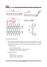
Страница 20: ...8 PACKAGING INFORMATION AND PRODUCTION INSTRUCTIONS WBR3L PCB Layout is shown as belows 17 25 ...
Страница 25: ...8 PACKAGING INFORMATION AND PRODUCTION INSTRUCTIONS 8 6 Storage Conditions 22 25 ...


